
Service Manual
Page 3
Contents Chapter 1 System Overview 1-1 System Features 1-1 System Memory 1-5 Advanced Expansion Subsystem 1-6 Integrated Server Management 1-6 Video Controller 1-6 Integrated SCSI Controller 1-6 SCSI Hard-Disk Drives 1-7 SCSI Configuration Guidelines 1-7 SCSI ID Numbers 1-7 Device Termination 1-8 System Unit 1-10 System Power Supply 1-10 Pin Assignments for the DC Power Connectors 1-10 DC Power Distribution 1-12 System Board Layout 1-14 System Board Jumpers 1-15 Interrupt Assignments 1-17 DMA Channel Assignments 1-18 Technical Specifications 1-19 v
Contents Chapter 1 System Overview 1-1 System Features 1-1 System Memory 1-5 Advanced Expansion Subsystem 1-6 Integrated Server Management 1-6 Video Controller 1-6 Integrated SCSI Controller 1-6 SCSI Hard-Disk Drives 1-7 SCSI Configuration Guidelines 1-7 SCSI ID Numbers 1-7 Device Termination 1-8 System Unit 1-10 System Power Supply 1-10 Pin Assignments for the DC Power Connectors 1-10 DC Power Distribution 1-12 System Board Layout 1-14 System Board Jumpers 1-15 Interrupt Assignments 1-17 DMA Channel Assignments 1-18 Technical Specifications 1-19 v
Service Manual
Page 9
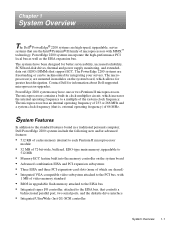
...SCSI controller System Overview 1-1 PowerEdge 2200 systems incorporate the high-performance PCI local bus as well as the EISA expansion bus. Contact Dell for integrating your servers. Chapter 1 System Overview The Dell® PowerEdge® 2200 systems are high-speed, upgradable, server systems that support ECC. ...Pentium® II family of microprocessors with 1 MB of video memory standard • BIOS in a traditional personal computer, Dell PowerEdge 2200 systems include the following new and/or advanced features: • 512 KB of cache memory internal to each Pentium II...
...SCSI controller System Overview 1-1 PowerEdge 2200 systems incorporate the high-performance PCI local bus as well as the EISA expansion bus. Contact Dell for integrating your servers. Chapter 1 System Overview The Dell® PowerEdge® 2200 systems are high-speed, upgradable, server systems that support ECC. ...Pentium® II family of microprocessors with 1 MB of video memory standard • BIOS in a traditional personal computer, Dell PowerEdge 2200 systems include the following new and/or advanced features: • 512 KB of cache memory internal to each Pentium II...
Service Manual
Page 10
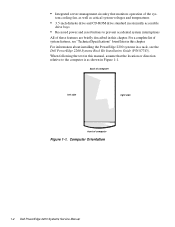
... following the text in this manual, assume that monitors operation of the sys- For a complete list of system features, see the Dell PowerEdge 2200 Systems Rack Kit Installation Guide (P/N 87743). • Integrated server management circuitry that the location or direction relative to the computer is as critical system voltages and temperatures • 3.5-inch diskette...
... following the text in this manual, assume that monitors operation of the sys- For a complete list of system features, see the Dell PowerEdge 2200 Systems Rack Kit Installation Guide (P/N 87743). • Integrated server management circuitry that the location or direction relative to the computer is as critical system voltages and temperatures • 3.5-inch diskette...

Service Manual
Page 14
... cards, Plug and Play ISA expansion cards, and PCI expansion cards. Integrated Server Management The system board contains integrated server management circuitry that might arise from such an arrangement. The integrated server management circuitry works in Chapter 4 for using it to the PCI local bus... cage, the CD-ROM drive in the middle externally accessible drive bay, and a SCSI drive installed in Chapter 7 of the Dell PowerEdge 2200 Systems User's Guide. The six expansion-card slots include three EISA expansion-card connectors and three PCI expansion-card connectors. The expansion...
... cards, Plug and Play ISA expansion cards, and PCI expansion cards. Integrated Server Management The system board contains integrated server management circuitry that might arise from such an arrangement. The integrated server management circuitry works in Chapter 4 for using it to the PCI local bus... cage, the CD-ROM drive in the middle externally accessible drive bay, and a SCSI drive installed in Chapter 7 of the Dell PowerEdge 2200 Systems User's Guide. The six expansion-card slots include three EISA expansion-card connectors and three PCI expansion-card connectors. The expansion...

Service Manual
Page 22
... microprocessor module (PROC_2) hard-disk drive access indicator connector (HDLED) auxiliary fan connector (AUXFAN) configuration jumpers PCI connectors (PCI4 [bottom], PCI5, and PCI6) server management connector (SVR_MGT) 1-14 Dell PowerEdge 2200 Systems Service Manual diskette controller connector (FLOPPY) fan connector (FAN) keyboard (bottom) and mouse (top) connectors (KYBD/MOUSE) serial port 1 (bottom) and serial...
... microprocessor module (PROC_2) hard-disk drive access indicator connector (HDLED) auxiliary fan connector (AUXFAN) configuration jumpers PCI connectors (PCI4 [bottom], PCI5, and PCI6) server management connector (SVR_MGT) 1-14 Dell PowerEdge 2200 Systems Service Manual diskette controller connector (FLOPPY) fan connector (FAN) keyboard (bottom) and mouse (top) connectors (KYBD/MOUSE) serial port 1 (bottom) and serial...
Service Manual
Page 33
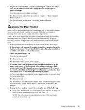
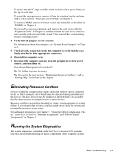
... you have performed an external visual inspection as described in this procedure require observation of system functions and indications, some of the keyboard. Insert the Dell Server Assistant CD into the CD-ROM drive. Do these steps: 1. To observe problem indications during the boot routine. Press the reset button or to the...
... you have performed an external visual inspection as described in this procedure require observation of system functions and indications, some of the keyboard. Insert the Dell Server Assistant CD into the CD-ROM drive. Do these steps: 1. To observe problem indications during the boot routine. Press the reset button or to the...

Service Manual
Page 34
Observe the monitor screen for the Dell Server Assistant main menu. Internal Visual Inspection CAUTION: Before you perform the visual inspection, refer to "System Features" in Chapter 1 to or from the drives. To ... to cool before touching it has had sufficient time to the next section, "Internal Visual Inspection." When you proceed with a metal surface on the chassis. 2-4 Dell PowerEdge 2200 Systems Service Manual Verify that the user has saved all open files and exited all the AC power cables from the power supply. 2. Does the...
Observe the monitor screen for the Dell Server Assistant main menu. Internal Visual Inspection CAUTION: Before you perform the visual inspection, refer to "System Features" in Chapter 1 to or from the drives. To ... to cool before touching it has had sufficient time to the next section, "Internal Visual Inspection." When you proceed with a metal surface on the chassis. 2-4 Dell PowerEdge 2200 Systems Service Manual Verify that the user has saved all open files and exited all the AC power cables from the power supply. 2. Does the...
Service Manual
Page 35
... you need to two or more devices. Proceed to the next section, "Eliminating Resource Conflicts," and to their power sources, and turn them on the Dell Server Assistant CD) contains tests that aid in troubleshooting all jumpers are firmly attached to "Getting Help" found later in disorderly or erratic system operation or...
... you need to two or more devices. Proceed to the next section, "Eliminating Resource Conflicts," and to their power sources, and turn them on the Dell Server Assistant CD) contains tests that aid in troubleshooting all jumpers are firmly attached to "Getting Help" found later in disorderly or erratic system operation or...

Service Manual
Page 36
..., make a blank, formatted diskette to be rebooted to run the selection. For instructions, see the chapter titled, "Getting Help," in the Diagnostics and Troubleshooting Guide. 2-6 Dell PowerEdge 2200 Systems Service Manual The system reboots to the Dell Server Assistant main menu (without mouse support).
..., make a blank, formatted diskette to be rebooted to run the selection. For instructions, see the chapter titled, "Getting Help," in the Diagnostics and Troubleshooting Guide. 2-6 Dell PowerEdge 2200 Systems Service Manual The system reboots to the Dell Server Assistant main menu (without mouse support).
Service Manual
Page 39
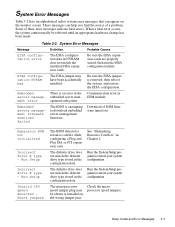
then run the EISA configuration utility. Embedded There is attempting to download embedded server management firmware. Embedded server management firmware download failed The BIOS is an error in the server manage- Beep Codes and Error Messages 3-3 When a fatal error occurs, the ...; System Error Messages Message Definition Probable Causes EISA configuration error The EISA configuration data in the configuration data. embedded server man- Run the System Setup program to restore your system configuration. Download of a problem. The diskette drive does...
then run the EISA configuration utility. Embedded There is attempting to download embedded server management firmware. Embedded server management firmware download failed The BIOS is an error in the server manage- Beep Codes and Error Messages 3-3 When a fatal error occurs, the ...; System Error Messages Message Definition Probable Causes EISA configuration error The EISA configuration data in the configuration data. embedded server man- Run the System Setup program to restore your system configuration. Download of a problem. The diskette drive does...
Service Manual
Page 57
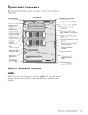
... (PROC_1) secondary microprocessor module (PROC_2) hard-disk drive access indicator connector (HDLED) auxiliary fan connector (AUXFAN) configuration jumpers PCI connectors (PCI4 [bottom], PCI5, and PCI6) server management connector (SVR_MGT) DIMMs NOTE: Use care when removing or replacing DIMMs. The available area of computer Figure 4-14.
... (PROC_1) secondary microprocessor module (PROC_2) hard-disk drive access indicator connector (HDLED) auxiliary fan connector (AUXFAN) configuration jumpers PCI connectors (PCI4 [bottom], PCI5, and PCI6) server management connector (SVR_MGT) DIMMs NOTE: Use care when removing or replacing DIMMs. The available area of computer Figure 4-14.

Service Manual
Page 80
... connector, 4-15 help, getting, 2-6 I ID numbers, SCSI devices, 1-7 indicators, 1-3 initial procedures, 2-1 initialization, system error messages, 3-3 insert removal, front-bezel, 4-5 integrated SCSI controller, 1-6 server management, 1-6 video controller, 1-6 interrupt assignments list of, 1-17 J jumpers descriptions, 1-16 list of, 1-16 location on system board, 1-15 JVGA connector, 4-15 K KYBD connector, 4-15 2 Dell PowerEdge 2200 Systems Service Manual
... connector, 4-15 help, getting, 2-6 I ID numbers, SCSI devices, 1-7 indicators, 1-3 initial procedures, 2-1 initialization, system error messages, 3-3 insert removal, front-bezel, 4-5 integrated SCSI controller, 1-6 server management, 1-6 video controller, 1-6 interrupt assignments list of, 1-17 J jumpers descriptions, 1-16 list of, 1-16 location on system board, 1-15 JVGA connector, 4-15 K KYBD connector, 4-15 2 Dell PowerEdge 2200 Systems Service Manual


