
Service Manual
Page 3
Contents Chapter 1 System Overview 1-1 System Features 1-1 System Memory 1-5 Advanced Expansion Subsystem 1-6 Integrated Server Management 1-6 Video Controller 1-6 Integrated SCSI Controller 1-6 SCSI Hard-Disk Drives 1-7 SCSI Configuration Guidelines 1-7 SCSI ID Numbers 1-7 Device Termination 1-8 System Unit 1-10 System Power Supply 1-10 Pin Assignments for the DC Power Connectors 1-10 DC Power Distribution 1-12 System Board Layout 1-14 System Board Jumpers 1-15 Interrupt Assignments 1-17 DMA Channel Assignments 1-18 Technical Specifications 1-19 v
Contents Chapter 1 System Overview 1-1 System Features 1-1 System Memory 1-5 Advanced Expansion Subsystem 1-6 Integrated Server Management 1-6 Video Controller 1-6 Integrated SCSI Controller 1-6 SCSI Hard-Disk Drives 1-7 SCSI Configuration Guidelines 1-7 SCSI ID Numbers 1-7 Device Termination 1-8 System Unit 1-10 System Power Supply 1-10 Pin Assignments for the DC Power Connectors 1-10 DC Power Distribution 1-12 System Board Layout 1-14 System Board Jumpers 1-15 Interrupt Assignments 1-17 DMA Channel Assignments 1-18 Technical Specifications 1-19 v

Service Manual
Page 6
... From the System Board 4-20 Figure 4-22. Table 1-3. Table 3-2. Table A-4. DC Voltage Ranges 1-10 Jumper Descriptions 1-16 Interrupt Assignments 1-17 DREQ Line Assignments 1-18 Technical Specifications 1-19 POST Beep Codes 3-1 System Error Messages 3-3 Key Functions A-2 Main Menu Categories A-4 Boot Options Submenu Categories A-5 Advanced Menu Categories A-7 Security Menu Categories A-9 Exit Menu Categories...
... From the System Board 4-20 Figure 4-22. Table 1-3. Table 3-2. Table A-4. DC Voltage Ranges 1-10 Jumper Descriptions 1-16 Interrupt Assignments 1-17 DREQ Line Assignments 1-18 Technical Specifications 1-19 POST Beep Codes 3-1 System Error Messages 3-3 Key Functions A-2 Main Menu Categories A-4 Boot Options Submenu Categories A-5 Advanced Menu Categories A-7 Security Menu Categories A-9 Exit Menu Categories...
Service Manual
Page 10
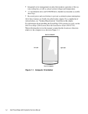
... text in this chapter. For information about installing the PowerEdge 2200 systems in a rack, see "Technical Specifications" found later in this manual, assume that the location or direction relative to prevent accidental system interruptions All of computer Figure 1-1. Computer Orientation 1-2 Dell PowerEdge 2200 Systems Service Manual tem cooling fan, as well as ... to the computer is as shown in Figure 1-1. • Integrated server management circuitry that monitors operation of system features, see the Dell PowerEdge 2200 Systems Rack Kit Installation Guide (P/N 87743).
... text in this chapter. For information about installing the PowerEdge 2200 systems in a rack, see "Technical Specifications" found later in this manual, assume that the location or direction relative to prevent accidental system interruptions All of computer Figure 1-1. Computer Orientation 1-2 Dell PowerEdge 2200 Systems Service Manual tem cooling fan, as well as ... to the computer is as shown in Figure 1-1. • Integrated server management circuitry that monitors operation of system features, see the Dell PowerEdge 2200 Systems Rack Kit Installation Guide (P/N 87743).

Service Manual
Page 27
... 266 MHz and an external operating frequency of 66 MHz Microprocessor speed 233 or 266 MHz Internal cache 512 KB L2 cache Math coprocessor . . . . . Technical Specifications Table 1-5. internal to the microprocessor System Information System chip set Intel 440FX controller chip set Data bus width 64 bits Address bus width. . . . . 32 bits...-pin sockets DIMM capacities . . . . . 32 and 128 MB (DIMMs are 60 ns or faster, buffered EDO) Standard RAM 32 MB (minimum) System Overview 1-19 Technical Specifications Microprocessor Microprocessor type . . .
... 266 MHz and an external operating frequency of 66 MHz Microprocessor speed 233 or 266 MHz Internal cache 512 KB L2 cache Math coprocessor . . . . . Technical Specifications Table 1-5. internal to the microprocessor System Information System chip set Intel 440FX controller chip set Data bus width 64 bits Address bus width. . . . . 32 bits...-pin sockets DIMM capacities . . . . . 32 and 128 MB (DIMMs are 60 ns or faster, buffered EDO) Standard RAM 32 MB (minimum) System Overview 1-19 Technical Specifications Microprocessor Microprocessor type . . .
Service Manual
Page 28
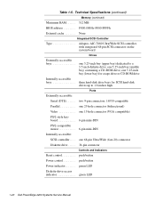
Technical Specifications (continued) Memory (continued) Maximum RAM 512 MB BIOS address F000:0000h-F000:FFFFh External cache None Integrated SCSI Controller Type Adaptec AIC-7880 Ultra/Wide ... . . . . . 34-pin connector Controls and Indicators Reset control push button Power control push button Power indicator green LED Diskette-drive access indicator green LED 1-20 Dell PowerEdge 2200 Systems Service Manual Table 1-5.
Technical Specifications (continued) Memory (continued) Maximum RAM 512 MB BIOS address F000:0000h-F000:FFFFh External cache None Integrated SCSI Controller Type Adaptec AIC-7880 Ultra/Wide ... . . . . . 34-pin connector Controls and Indicators Reset control push button Power control push button Power indicator green LED Diskette-drive access indicator green LED 1-20 Dell PowerEdge 2200 Systems Service Manual Table 1-5.
Service Manual
Page 29
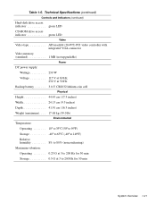
Technical Specifications (continued) Controls and Indicators (continued) Hard-disk drive access indicator green LED CD-ROM drive access indicator green LED Video Video type ATI mach64 (264VT) ...
Technical Specifications (continued) Controls and Indicators (continued) Hard-disk drive access indicator green LED CD-ROM drive access indicator green LED Video Video type ATI mach64 (264VT) ...

Service Manual
Page 30
Table 1-5. Technical Specifications (continued) Environmental (continued) Maximum shock: Operating half-sine wave form: 50 G for 2 ms Storage half-sine wave form: 110 G for 15 ms Altitude: Operating 16 to 3048 m (-50 to 10,000 ft) Storage 16 to 10,600 m (-50 to 35,000 ft) z 1-22 Dell PowerEdge 2200 Systems Service Manual square wave form: 27 G for 2 ms;
Table 1-5. Technical Specifications (continued) Environmental (continued) Maximum shock: Operating half-sine wave form: 50 G for 2 ms Storage half-sine wave form: 110 G for 15 ms Altitude: Operating 16 to 3048 m (-50 to 10,000 ft) Storage 16 to 10,600 m (-50 to 35,000 ft) z 1-22 Dell PowerEdge 2200 Systems Service Manual square wave form: 27 G for 2 ms;

Service Manual
Page 36
.... 2-6 Dell PowerEdge 2200 Systems Service Manual Select Run System Diagnostics under the Run System Utilities option. A message appears indicating that the diagnostics program can record critical messages and information as necessary. Runs all test groups to quickly locate a failure or to indicate where further testing is needed to isolate a failure • Run Specific Tests...
.... 2-6 Dell PowerEdge 2200 Systems Service Manual Select Run System Diagnostics under the Run System Utilities option. A message appears indicating that the diagnostics program can record critical messages and information as necessary. Runs all test groups to quickly locate a failure or to indicate where further testing is needed to isolate a failure • Run Specific Tests...
Service Manual
Page 67
... addition to the left of the selection. These selections are : • Main menu - tions and setting selections or setting information • Help box - Displays item-specific help for the item where the cursor is presented (see Figure A-1): • Title box - then shut down the system and try again. The initial screen...
... addition to the left of the selection. These selections are : • Main menu - tions and setting selections or setting information • Help box - Displays item-specific help for the item where the cursor is presented (see Figure A-1): • Title box - then shut down the system and try again. The initial screen...

Service Manual
Page 69
... help box title box Dell System PowerEdge 2200 Setup Main Advanced Security Exit Time: [5:01:96] Date: [June 04, 1997] Diskette Drive A: [1.44 MB, 3.5 inch] Diskette Drive B: [Not Installed] Fast Video BIOS: [On and Cached] Memory Cache: [Enable] Boot Sequence: [A: then C:] Numlock: [On] Speaker: [On] BIOS Version AXX Item Specific Help Resets the time...
... help box title box Dell System PowerEdge 2200 Setup Main Advanced Security Exit Time: [5:01:96] Date: [June 04, 1997] Diskette Drive A: [1.44 MB, 3.5 inch] Diskette Drive B: [Not Installed] Fast Video BIOS: [On and Cached] Memory Cache: [Enable] Boot Sequence: [A: then C:] Numlock: [On] Speaker: [On] BIOS Version AXX Item Specific Help Resets the time...

Service Manual
Page 71
... button on the front bezel System Setup Program A-5 Boot Options Submenu Dell System PowerEdge 2200 Setup Main Advanced Security Exit Boot Options Boot Sequence: [A: then C:] SETUP Prompt: [Enabled] POST Errors: [Enabled] Diskette Drive Check: [Enabled] Reset Button: [Enabled] BIOS Version AXX Item Specific Help Determines the order of drives from which the system tries...
... button on the front bezel System Setup Program A-5 Boot Options Submenu Dell System PowerEdge 2200 Setup Main Advanced Security Exit Boot Options Boot Sequence: [A: then C:] SETUP Prompt: [Enabled] POST Errors: [Enabled] Diskette Drive Check: [Enabled] Reset Button: [Enabled] BIOS Version AXX Item Specific Help Determines the order of drives from which the system tries...

Service Manual
Page 72
Advanced Menu A-6 Dell PowerEdge 2200 Systems Service Manual Advanced Menu Dell System PowerEdge 2200 Setup Main Advanced Security Exit Serial Port 1: Serial Port 2: Parallel Port: Parallel Mode: Diskette Controller: Onboard SCSI: PCI Scan Sequence Use MP specification PS/2 Mouse [AUTO] [AUTO] [378, IRQ 7] [Output only] [Enabled] [Enabled] [Slot devices first] [1.4] [Enabled] BIOS Version AXX Item Specific Help Configures the...
Advanced Menu A-6 Dell PowerEdge 2200 Systems Service Manual Advanced Menu Dell System PowerEdge 2200 Setup Main Advanced Security Exit Serial Port 1: Serial Port 2: Parallel Port: Parallel Mode: Diskette Controller: Onboard SCSI: PCI Scan Sequence Use MP specification PS/2 Mouse [AUTO] [AUTO] [378, IRQ 7] [Output only] [Enabled] [Enabled] [Slot devices first] [1.4] [Enabled] BIOS Version AXX Item Specific Help Configures the...

Service Manual
Page 73
Serial Port 2 Selects a unique address and interrupt request for LPT Port. Use MP Specifications Configures the Multiprocessor Specification level. PS/2 Mouse Enables (default) or disables the built-in diskette controller. Table A-4. and Auto (default). and Auto (default). Auto selects the next available combination. ...
Serial Port 2 Selects a unique address and interrupt request for LPT Port. Use MP Specifications Configures the Multiprocessor Specification level. PS/2 Mouse Enables (default) or disables the built-in diskette controller. Table A-4. and Auto (default). and Auto (default). Auto selects the next available combination. ...
Service Manual
Page 74
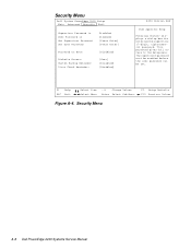
... Reminder: Virus Check Reminder: Disabled Disabled [Press Enter] [Press Enter] [Disabled] [User] [Disabled] [Disabled] BIOS Version AXX Item Specific Help Pressing displays a dialog box for entering the supervisor (7-digit, alphanumeric) password. Security Menu A-8 Dell PowerEdge 2200 Systems Service Manual The supervisor password must be enabled before the user password can be set. This password...
... Reminder: Virus Check Reminder: Disabled Disabled [Press Enter] [Press Enter] [Disabled] [User] [Disabled] [Disabled] BIOS Version AXX Item Specific Help Pressing displays a dialog box for entering the supervisor (7-digit, alphanumeric) password. Security Menu A-8 Dell PowerEdge 2200 Systems Service Manual The supervisor password must be enabled before the user password can be set. This password...

Service Manual
Page 76
Exit Menu Dell System PowerEdge 2200 Setup Main Advanced Security Exit Save Changes & Exit Exit Without Saving Changes Get Default Values Load Previous Values Save Changes BIOS Version AXX Item Specific Help Saves all changes made in the Setup program to CMOS, exits the Setup program, and then reboots the computer. Exit Menu F9 Setup Defaults F10 Previous Values A-10 Dell PowerEdge 2200 Systems Service Manual F1 Help ESC Exit Select Item Select Menu -/+ Change Values Enter Select Sub-Menu Figure A-5.
Exit Menu Dell System PowerEdge 2200 Setup Main Advanced Security Exit Save Changes & Exit Exit Without Saving Changes Get Default Values Load Previous Values Save Changes BIOS Version AXX Item Specific Help Saves all changes made in the Setup program to CMOS, exits the Setup program, and then reboots the computer. Exit Menu F9 Setup Defaults F10 Previous Values A-10 Dell PowerEdge 2200 Systems Service Manual F1 Help ESC Exit Select Item Select Menu -/+ Change Values Enter Select Sub-Menu Figure A-5.
Service Manual
Page 79
... power, 1-12 CD-ROM drive access indicator location, 1-3 location, 1-4, 4-8 removal, 4-9 computer back/left side internal view, 1-5 cover removal, 4-3 front/right side internal view, 1-4 orientation, 1-2 technical specifications, 1-19 configuration guidelines SCSI drives, 1-7 configuration jumpers descriptions, 1-16 locations, 1-14, 1-15, 4-15 connectors locations, 1-14, 4-15 control panel assembly location, 1-4 removal, 4-7 D DC power connectors...
... power, 1-12 CD-ROM drive access indicator location, 1-3 location, 1-4, 4-8 removal, 4-9 computer back/left side internal view, 1-5 cover removal, 4-3 front/right side internal view, 1-4 orientation, 1-2 technical specifications, 1-19 configuration guidelines SCSI drives, 1-7 configuration jumpers descriptions, 1-16 locations, 1-14, 1-15, 4-15 connectors locations, 1-14, 4-15 control panel assembly location, 1-4 removal, 4-7 D DC power connectors...
Service Manual
Page 81
See drives SERIAL connector, 4-15 specifications, technical, 1-19 subsystems, advanced expansion, 1-6 SVR_MGT connector, 4-15 system battery removal, 4-23 system board assembly, removal, 4-17 component locations, 1-14, 4-15 illustrated, 1-14 jumpers, 1-15 ...
See drives SERIAL connector, 4-15 specifications, technical, 1-19 subsystems, advanced expansion, 1-6 SVR_MGT connector, 4-15 system battery removal, 4-23 system board assembly, removal, 4-17 component locations, 1-14, 4-15 illustrated, 1-14 jumpers, 1-15 ...

Service Manual
Page 82
... combinations, A-3 screen conventions, A-1 Security menu, A-8 starting, A-1 T technical specifications, 1-19 TEMP_1 connector, 4-15 TEMP_2 connector, 4-15 termination jumpers SCSI drives, 1-8 terminator card removal, 4-21 troubleshooting boot routine, observing, 2-3 external visual inspection, 2-2 initial procedures, 2-1 initial user contact, 2-1 internal visual inspection, 2-4 U user contact, initial, 2-1 V video controller, integrated, 1-6 visual inspection external, 2-2 internal, 2-4 4 Dell PowerEdge 2200 Systems Service Manual
... combinations, A-3 screen conventions, A-1 Security menu, A-8 starting, A-1 T technical specifications, 1-19 TEMP_1 connector, 4-15 TEMP_2 connector, 4-15 termination jumpers SCSI drives, 1-8 terminator card removal, 4-21 troubleshooting boot routine, observing, 2-3 external visual inspection, 2-2 initial procedures, 2-1 initial user contact, 2-1 internal visual inspection, 2-4 U user contact, initial, 2-1 V video controller, integrated, 1-6 visual inspection external, 2-2 internal, 2-4 4 Dell PowerEdge 2200 Systems Service Manual
