Service Manual
Page 6
... supply, 1-10 cables, 1-12 connectors, 1-10 DC voltage ranges, 1-10 illustrated, 1-12 power distribution diagram, 1-13 removal, 4-12 precautionary measures, 4-2 R reset button, 1-3 resource conflicts, eliminating, 2-5 2 Dell PowerEdge 2100/180 and 2100/200 Systems Service Manual
... supply, 1-10 cables, 1-12 connectors, 1-10 DC voltage ranges, 1-10 illustrated, 1-12 power distribution diagram, 1-13 removal, 4-12 precautionary measures, 4-2 R reset button, 1-3 resource conflicts, eliminating, 2-5 2 Dell PowerEdge 2100/180 and 2100/200 Systems Service Manual

Service Manual
Page 15
... Pro microprocessor and all other elements of 66 MHz System Overview 1-1 PowerEdge 2100 systems incorporate the highperformance peripheral component interconnect (PCI) local bus as well as follows: • Dell PowerEdge 2100/180 system - 180 MHz derived from a system clock frequency of 60 MHz • Dell PowerEdge 2100/200 system - 200 MHz derived from a system clock frequency of the...
... Pro microprocessor and all other elements of 66 MHz System Overview 1-1 PowerEdge 2100 systems incorporate the highperformance peripheral component interconnect (PCI) local bus as well as follows: • Dell PowerEdge 2100/180 system - 180 MHz derived from a system clock frequency of 60 MHz • Dell PowerEdge 2100/200 system - 200 MHz derived from a system clock frequency of the...
Service Manual
Page 16
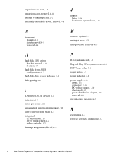
tion about QUICK TEST, see "Technical Specifications" found in a traditional personal computer, Dell PowerEdge 2100 systems include the following new and/or advanced features: • 256 KB of cache memory internal to the Pentium Pro module • ...list of system features, see "Running the Diskette-Based Diagnostics" in Chapter 2.) All of the expansion-card slots are briefly described in this chapter. 1-2 Dell PowerEdge 2100/180 and 2100/200 Systems Service Manual tem cooling fan for more informa- System Features In addition to the standard features found later in this chapter.
tion about QUICK TEST, see "Technical Specifications" found in a traditional personal computer, Dell PowerEdge 2100 systems include the following new and/or advanced features: • 256 KB of cache memory internal to the Pentium Pro module • ...list of system features, see "Running the Diskette-Based Diagnostics" in Chapter 2.) All of the expansion-card slots are briefly described in this chapter. 1-2 Dell PowerEdge 2100/180 and 2100/200 Systems Service Manual tem cooling fan for more informa- System Features In addition to the standard features found later in this chapter.
Service Manual
Page 18
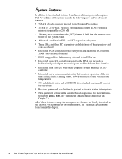
system power supply control panel assembly diskette drive CD-ROM drive third drive bay diskette controller cable power cables control panel cable SCSI cable system cooling fan internal hard-disk drive cage Figure 1-3. Front/Right Side Internal View system board mounting plate 1-4 Dell PowerEdge 2100/180 and 2100/200 Systems Service Manual
system power supply control panel assembly diskette drive CD-ROM drive third drive bay diskette controller cable power cables control panel cable SCSI cable system cooling fan internal hard-disk drive cage Figure 1-3. Front/Right Side Internal View system board mounting plate 1-4 Dell PowerEdge 2100/180 and 2100/200 Systems Service Manual
Service Manual
Page 20
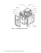
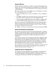
... support a mixture of the slowest DIMM installed. • The largest capacity DIMM should be in socket DIMM_A with the Intel LANDesk® Server Management suite. 1-6 Dell PowerEdge 2100/180 and 2100/200 Systems Service Manual System Memory System memory has a minimum of 16 MB of the sys-
... support a mixture of the slowest DIMM installed. • The largest capacity DIMM should be in socket DIMM_A with the Intel LANDesk® Server Management suite. 1-6 Dell PowerEdge 2100/180 and 2100/200 Systems Service Manual System Memory System memory has a minimum of 16 MB of the sys-
Service Manual
Page 22
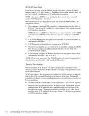
... ID 6. • The drive you intend to use the following text. Figure 1-5 shows some examples of whether you must have a unique SCSI ID number from Dell, the default SCSI ID numbers are shipped from 0 to any other drives installed in the SCSI hard-disk drive cage. NOTE: If only wide SCSI... configure any additional hard-disk drives to 15. no requirement that SCSI ID numbers be assigned sequentially or that end, regardless of SCSI termination jumpers. 1-8 Dell PowerEdge 2100/180 and 2100/200 Systems Service Manual Termination should be configured as SCSI ID 0.
... ID 6. • The drive you intend to use the following text. Figure 1-5 shows some examples of whether you must have a unique SCSI ID number from Dell, the default SCSI ID numbers are shipped from 0 to any other drives installed in the SCSI hard-disk drive cage. NOTE: If only wide SCSI... configure any additional hard-disk drives to 15. no requirement that SCSI ID numbers be assigned sequentially or that end, regardless of SCSI termination jumpers. 1-8 Dell PowerEdge 2100/180 and 2100/200 Systems Service Manual Termination should be configured as SCSI ID 0.

Service Manual
Page 24
... -5.50 VDC 0.3 A +5 VFP3 +4.75 to their corresponding power input connectors on +5 VDC and +3.3 VDC shall not exceed 170 W. 2 The total power of the connectors. 1-10 Dell PowerEdge 2100/180 and 2100/200 Systems Service Manual
... -5.50 VDC 0.3 A +5 VFP3 +4.75 to their corresponding power input connectors on +5 VDC and +3.3 VDC shall not exceed 170 W. 2 The total power of the connectors. 1-10 Dell PowerEdge 2100/180 and 2100/200 Systems Service Manual

Service Manual
Page 26
DC Power Cables 1-12 Dell PowerEdge 2100/180 and 2100/200 Systems Service Manual DC Power Connectors P7 DC Power Distribution Figures 1-9 and 1-10 provide the following information about DC power distribution: • Power-supply connector identification • Power cable connections for diskette, tape, CD-ROM, and hard-disk drives • Power distribution to sockets and connectors on the system board P1 P4 P5 P7 P6 P3 P2 Figure 1-9. P7 1 2 34 5 6 +3.3 VDC (blue/white) +3.3 VDC (blue/white) +3.3 VDC (blue/white) common (black) common (black) common (black) Figure 1-8.
DC Power Cables 1-12 Dell PowerEdge 2100/180 and 2100/200 Systems Service Manual DC Power Connectors P7 DC Power Distribution Figures 1-9 and 1-10 provide the following information about DC power distribution: • Power-supply connector identification • Power cable connections for diskette, tape, CD-ROM, and hard-disk drives • Power distribution to sockets and connectors on the system board P1 P4 P5 P7 P6 P3 P2 Figure 1-9. P7 1 2 34 5 6 +3.3 VDC (blue/white) +3.3 VDC (blue/white) +3.3 VDC (blue/white) common (black) common (black) common (black) Figure 1-8.

Service Manual
Page 28
System Board Components 1-14 Dell PowerEdge 2100/180 and 2100/200 Systems Service Manual fan connector (FAN) integrated SCSI port connector (SCSI) top of the computer 3-volt power connector (POWER3V) keyboard (bottom) and mouse (top) ...
System Board Components 1-14 Dell PowerEdge 2100/180 and 2100/200 Systems Service Manual fan connector (FAN) integrated SCSI port connector (SCSI) top of the computer 3-volt power connector (POWER3V) keyboard (bottom) and mouse (top) ...
Service Manual
Page 30
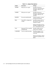
... Description Settings Microprocessor speed Installed if the microprocessor's internal speed is 180 MHz, otherwise, not installed. Remove the jumper to boot system from BIOS. 1-16 Dell PowerEdge 2100/180 and 2100/200 Systems Service Manual Password enable/disable Jumper installed to configure the system. Jumper 200MHZ 180MHZ PASSWD EISA VGA CARDBIOS Table 1-2.
... Description Settings Microprocessor speed Installed if the microprocessor's internal speed is 180 MHz, otherwise, not installed. Remove the jumper to boot system from BIOS. 1-16 Dell PowerEdge 2100/180 and 2100/200 Systems Service Manual Password enable/disable Jumper installed to configure the system. Jumper 200MHZ 180MHZ PASSWD EISA VGA CARDBIOS Table 1-2.

Service Manual
Page 34
... indicator green LED Diskette-drive access indicator green LED Hard-disk drive access indicator green LED CD-ROM drive access indicator green LED 1-20 Dell PowerEdge 2100/180 and 2100/200 Systems Service Manual one 15-hole connector (VGA compatible) PS/2-style keyboard 6-pin mini-DIN PS/2-compatible mouse 6-pin mini-DIN Internally accessible...
... indicator green LED Diskette-drive access indicator green LED Hard-disk drive access indicator green LED CD-ROM drive access indicator green LED 1-20 Dell PowerEdge 2100/180 and 2100/200 Systems Service Manual one 15-hole connector (VGA compatible) PS/2-style keyboard 6-pin mini-DIN PS/2-compatible mouse 6-pin mini-DIN Internally accessible...
Service Manual
Page 38
... controls, see "System Features" in Chapter 1. If one of the serial port connectors, and its captive screws must be necessary to replace the keyboard. 2-2 Dell PowerEdge 2100/180 and 2100/200 Systems Service Manual For a serial mouse, the mouse interface cable must be secure enough to ensure a firm connection. 4. The captive screws that no...
... controls, see "System Features" in Chapter 1. If one of the serial port connectors, and its captive screws must be necessary to replace the keyboard. 2-2 Dell PowerEdge 2100/180 and 2100/200 Systems Service Manual For a serial mouse, the mouse interface cable must be secure enough to ensure a firm connection. 4. The captive screws that no...
Service Manual
Page 40
... indicators light up during the boot routine. When you proceed with the internal visual inspection described in this chapter. Remove the system unit cover. 2-4 Dell PowerEdge 2100/180 and 2100/200 Systems Service Manual 4. If either of these steps: 1. NOTE: The system beeps once during the boot routine, troubleshoot the diskette drive or hard...
... indicators light up during the boot routine. When you proceed with the internal visual inspection described in this chapter. Remove the system unit cover. 2-4 Dell PowerEdge 2100/180 and 2100/200 Systems Service Manual 4. If either of these steps: 1. NOTE: The system beeps once during the boot routine, troubleshoot the diskette drive or hard...
Service Manual
Page 42
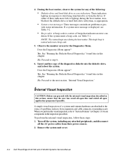
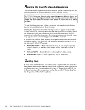
...following options or exit to isolate a failure • RUN ALL TESTS - Starting the diagnostics causes the Dell logo screen to appear on the monitor screen, followed by a message indicating that aid in troubleshooting all...loads, a program tests the portion of main memory (RAM) required for a thorough test of the problem, call Dell for technical assistance. Runs all test groups to quickly locate a failure or to the proper troubleshooting steps for determining... errors are found in the Diagnostics and Troubleshooting Guide. 2-6 Dell PowerEdge 2100/180 and 2100/200 Systems Service Manual
...following options or exit to isolate a failure • RUN ALL TESTS - Starting the diagnostics causes the Dell logo screen to appear on the monitor screen, followed by a message indicating that aid in troubleshooting all...loads, a program tests the portion of main memory (RAM) required for a thorough test of the problem, call Dell for technical assistance. Runs all test groups to quickly locate a failure or to the proper troubleshooting steps for determining... errors are found in the Diagnostics and Troubleshooting Guide. 2-6 Dell PowerEdge 2100/180 and 2100/200 Systems Service Manual
Service Manual
Page 44
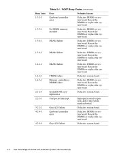
... or system board. DRAM failure Defective DIMMs or system board. Keyboard controller error Defective DIMMs or system board. Gate A20 failure Defective system board. 3-2 Dell PowerEdge 2100/180 and 2100/200 Systems Service Manual CMOS failure Defective system board. Reseat the DIMMs or replace the system board. Beep Code 1-3-1-3 1-3-3-1 1-3-4-1 1-3-4-3 1-4-1-1 1-4-2-1 1-4-3-1 2-1-2-3 2-2-3-1 3-2-2-1 4-2-4-3 4-2-4-4 Table 3-1. POST Beep Codes (Continued...
... or system board. DRAM failure Defective DIMMs or system board. Keyboard controller error Defective DIMMs or system board. Gate A20 failure Defective system board. 3-2 Dell PowerEdge 2100/180 and 2100/200 Systems Service Manual CMOS failure Defective system board. Reseat the DIMMs or replace the system board. Beep Code 1-3-1-3 1-3-3-1 1-3-4-1 1-3-4-3 1-4-1-1 1-4-2-1 1-4-3-1 2-1-2-3 2-2-3-1 3-2-2-1 4-2-4-3 4-2-4-4 Table 3-1. POST Beep Codes (Continued...

Service Manual
Page 46
... the installed EISA expansion cards. Defective keyboard, keyboard cable, or system board. Verify that the total installed DIMM memory does not exceed 256 MB. 3-4 Dell PowerEdge 2100/180 and 2100/200 Systems Service Manual System Error Messages (Continued) Message Definition Probable Causes Operating system not found The system did not find a bootable operating system...
... the installed EISA expansion cards. Defective keyboard, keyboard cable, or system board. Verify that the total installed DIMM memory does not exceed 256 MB. 3-4 Dell PowerEdge 2100/180 and 2100/200 Systems Service Manual System Error Messages (Continued) Message Definition Probable Causes Operating system not found The system did not find a bootable operating system...

Service Manual
Page 50
.... 2. Disconnect the computer and any attached peripherals from their power sources to discharge any of the computer to reduce the potential for your body. 4-2 Dell PowerEdge 2100/180 and 2100/200 Systems Service Manual face, such as the system power supply's fan guard, on the computer chassis. Turn off the computer and any communications...
.... 2. Disconnect the computer and any attached peripherals from their power sources to discharge any of the computer to reduce the potential for your body. 4-2 Dell PowerEdge 2100/180 and 2100/200 Systems Service Manual face, such as the system power supply's fan guard, on the computer chassis. Turn off the computer and any communications...

Service Manual
Page 52
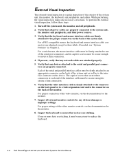
Pry the front bezel loose with your finger tips and remove it from the chassis. As you pry the front bezel loose, pry at different points around the bezel to keep the opening between the front bezel and the computer chassis equal on all sides to prevent damage to the bezel alignment pins. 4-4 Dell PowerEdge 2100/180 and 2100/200 Systems Service Manual Remove the computer cover. 2. Front Bezel Removal To remove the front bezel, follow these steps: 1. Front Bezel retaining holes (6) retaining clips (6) alignment holes (5) alignment pins (5) Figure 4-2.
Pry the front bezel loose with your finger tips and remove it from the chassis. As you pry the front bezel loose, pry at different points around the bezel to keep the opening between the front bezel and the computer chassis equal on all sides to prevent damage to the bezel alignment pins. 4-4 Dell PowerEdge 2100/180 and 2100/200 Systems Service Manual Remove the computer cover. 2. Front Bezel Removal To remove the front bezel, follow these steps: 1. Front Bezel retaining holes (6) retaining clips (6) alignment holes (5) alignment pins (5) Figure 4-2.

Service Manual
Page 54
Remove the control-panel-assembly cable from the PANEL connec- Disconnect the control-panel assembly cable from the hole in the chassis. 4-6 Dell PowerEdge 2100/180 and 2100/200 Systems Service Manual Lift the control panel assembly out of computer chassis tabs (2) Figure 4-4. Control Panel Assembly top of computer screw control panel assembly ...
Remove the control-panel-assembly cable from the PANEL connec- Disconnect the control-panel assembly cable from the hole in the chassis. 4-6 Dell PowerEdge 2100/180 and 2100/200 Systems Service Manual Lift the control panel assembly out of computer chassis tabs (2) Figure 4-4. Control Panel Assembly top of computer screw control panel assembly ...

Service Manual
Page 56
... record the power connector number and interface cable connector identification. 2. Disconnect the DC power cable and the interface cable from the drive (see Figure 4-7). 4-8 Dell PowerEdge 2100/180 and 2100/200 Systems Service Manual Remove the drive-mounting rails and drive-mounting extensions (if present) from the back of the externallyaccessible drive bays, follow...
... record the power connector number and interface cable connector identification. 2. Disconnect the DC power cable and the interface cable from the drive (see Figure 4-7). 4-8 Dell PowerEdge 2100/180 and 2100/200 Systems Service Manual Remove the drive-mounting rails and drive-mounting extensions (if present) from the back of the externallyaccessible drive bays, follow...


