
Information Update
Page 6
... fan module is removed from the system, all server modules (blades) in the system will be "throttled" until the power supply or fan module is normal behavior for these cards, and supersedes Table 1-11 in the server module (blade). NIC Activity LED The NIC ...panel may occasionally illuminate due to the KVM module rather than the server module front panel. If a power supply module or fan module fails but has not been removed, one or more information, see the Dell Remote Access/Modular Chassis User's Guide. 4 Information Update This will indicate if throttling of the server...
... fan module is removed from the system, all server modules (blades) in the system will be "throttled" until the power supply or fan module is normal behavior for these cards, and supersedes Table 1-11 in the server module (blade). NIC Activity LED The NIC ...panel may occasionally illuminate due to the KVM module rather than the server module front panel. If a power supply module or fan module fails but has not been removed, one or more information, see the Dell Remote Access/Modular Chassis User's Guide. 4 Information Update This will indicate if throttling of the server...
Configuration Guide
Page 7
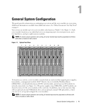
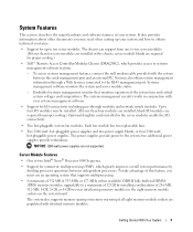
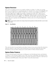
Additional information is inserted into an enclosure that supports power supplies, fan modules, a management module (Dell™ Remote Access Controller/Modular Chassis [DRAC/MC]), a keyboard/video/mouse (KVM) switch module, and at least one I/O module for network connectivity (see Figure 1-2.) The power supplies, fans, DRAC/MC, and I/O modules are shared resources for the server modules in...
Additional information is inserted into an enclosure that supports power supplies, fan modules, a management module (Dell™ Remote Access Controller/Modular Chassis [DRAC/MC]), a keyboard/video/mouse (KVM) switch module, and at least one I/O module for network connectivity (see Figure 1-2.) The power supplies, fans, DRAC/MC, and I/O modules are shared resources for the server modules in...

Configuration Guide
Page 8
... 1 7 KVM module 10 blanks (2) 9 2 fan modules (2) 5 Fibre Channel pass-through module 8 DRAC/MC module 11 I/O bay 4 3 Ethernet switch module 6 I/O bay 3 9 power supply modules (4) 12 blanks (2) Other Documents You May Need The Product Information Guide provides important safety and regulatory information. Warranty information may be included within this... components. • The Dell Remote Access Controller/Modular Chassis User's Guide provides detailed information on using the remote management features of the system. • The Dell PowerEdge Expandable RAID Controller 5iR Integrated...
... 1 7 KVM module 10 blanks (2) 9 2 fan modules (2) 5 Fibre Channel pass-through module 8 DRAC/MC module 11 I/O bay 4 3 Ethernet switch module 6 I/O bay 3 9 power supply modules (4) 12 blanks (2) Other Documents You May Need The Product Information Guide provides important safety and regulatory information. Warranty information may be included within this... components. • The Dell Remote Access Controller/Modular Chassis User's Guide provides detailed information on using the remote management features of the system. • The Dell PowerEdge Expandable RAID Controller 5iR Integrated...

Configuration Guide
Page 9
... Connect power to the power supplies. • The Baseboard Management Controller documentation provides detailed information on using the BMC. • The Dell OpenManage Server Assistant User's Guide provides detailed information on the systems management software applications, as well as information on support.dell.com and... components you purchased separately provides information to configure and install these options. • Updates are installed. NOTE: You should power up the enclosure prior to the KVM module. The Ethernet switch may take longer to boot than the server modules, which...
... Connect power to the power supplies. • The Baseboard Management Controller documentation provides detailed information on using the BMC. • The Dell OpenManage Server Assistant User's Guide provides detailed information on the systems management software applications, as well as information on support.dell.com and... components you purchased separately provides information to configure and install these options. • Updates are installed. NOTE: You should power up the enclosure prior to the KVM module. The Ethernet switch may take longer to boot than the server modules, which...
Getting Started Guide
Page 5
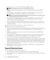
... server modules. (If fewer than four modules are installed, blank I/O modules are required for proper cooling.) • Dell™ Remote Access Controller/Modular Chassis (DRAC/MC), which greatly improves overall system performance by installing combinations of your system... Each fan module has two replaceable fans. • Two 2100-watt, hot-pluggable power supplies and two power supply blanks, or four 2100-watt, hot-pluggable power supplies. two additional power supplies provide redundancy. Embedded systems management circuitry that supports multiprocessing. • A minimum of ...
... server modules. (If fewer than four modules are installed, blank I/O modules are required for proper cooling.) • Dell™ Remote Access Controller/Modular Chassis (DRAC/MC), which greatly improves overall system performance by installing combinations of your system... Each fan module has two replaceable fans. • Two 2100-watt, hot-pluggable power supplies and two power supply blanks, or four 2100-watt, hot-pluggable power supplies. two additional power supplies provide redundancy. Embedded systems management circuitry that supports multiprocessing. • A minimum of ...
Getting Started Guide
Page 6
... video memory (nonupgradable). NOTE: Only Dell-supplied USB diskette drives and optical drives are supported; • Support for evaluating system components and devices. This video subsystem contains 16 MB of the system fans as well as a whole, including all of the server modules, network switch modules, power supplies, and fans. Maximum resolution is 1280...
... video memory (nonupgradable). NOTE: Only Dell-supplied USB diskette drives and optical drives are supported; • Support for evaluating system components and devices. This video subsystem contains 16 MB of the system fans as well as a whole, including all of the server modules, network switch modules, power supplies, and fans. Maximum resolution is 1280...
Getting Started Guide
Page 12
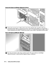
.... Connect the monitor's power cable to the system. The power indicators should light. Connect the System and Monitor (Optional) to Power Connect the system's power cable(s) to a grounded electrical outlet. Next, plug the other end of the cable into a grounded electrical outlet or a separate power source such as an uninterruptible power supply (UPS) or a power distribution unit (PDU).
.... Connect the monitor's power cable to the system. The power indicators should light. Connect the System and Monitor (Optional) to Power Connect the system's power cable(s) to a grounded electrical outlet. Next, plug the other end of the cable into a grounded electrical outlet or a separate power source such as an uninterruptible power supply (UPS) or a power distribution unit (PDU).
Getting Started Guide
Page 15
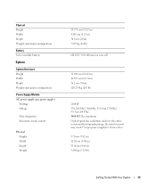
Physical Height Width Depth Weight (maximum configuration) Battery Server module battery System System Enclosure Height Width Depth Weight (maximum configuration) Power Supply Module AC power supply (per power supply for 10 ms or less. 9.70 cm (3.82 in) 12.90 cm (5.08 in) 23.01cm (9.06 in ) 129.274 kg (285... 3480 BTU/hr. maximum Under typical line conditions and over the entire system ambient operating range, the inrush current may reach 55 A per power supply) Wattage Voltage Heat dissipation Maximum inrush current Physical Height Width Depth Weight 28.575 cm (11.25 in) 4.241 cm (1.67 in) ...
Physical Height Width Depth Weight (maximum configuration) Battery Server module battery System System Enclosure Height Width Depth Weight (maximum configuration) Power Supply Module AC power supply (per power supply for 10 ms or less. 9.70 cm (3.82 in) 12.90 cm (5.08 in) 23.01cm (9.06 in ) 129.274 kg (285... 3480 BTU/hr. maximum Under typical line conditions and over the entire system ambient operating range, the inrush current may reach 55 A per power supply) Wattage Voltage Heat dissipation Maximum inrush current Physical Height Width Depth Weight 28.575 cm (11.25 in) 4.241 cm (1.67 in) ...
Hardware Owner's Manual (PDF)
Page 3
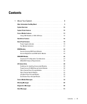
... 10 System Status Features 10 Server Module Features 12 Using USB Diskette or USB CD Drives 16 Hard-Drive Features 16 Back-Panel Features 18 Power Supply Indicator 19 Fan Module Indicators 21 KVM Modules 22 Avocent Analog KVM Switch Module 22 Avocent Digital Access KVM Switch Module 24 DRAC/MC Module...
... 10 System Status Features 10 Server Module Features 12 Using USB Diskette or USB CD Drives 16 Hard-Drive Features 16 Back-Panel Features 18 Power Supply Indicator 19 Fan Module Indicators 21 KVM Modules 22 Avocent Analog KVM Switch Module 22 Avocent Digital Access KVM Switch Module 24 DRAC/MC Module...
Hardware Owner's Manual (PDF)
Page 4
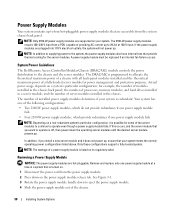
... 54 Baseboard Management Controller Configuration 54 Entering the BMC Setup Module 55 BMC Setup Module Options 55 3 Installing System Options 57 Power Supply Modules 58 System Power Guidelines 58 Removing a Power Supply Module 58 Installing a Power Supply Module 59 Fan Modules 59 Removing a Fan 60 Installing a Fan 61 DRAC/MC Module 61 Removing a DRAC/MC Module 61...
... 54 Baseboard Management Controller Configuration 54 Entering the BMC Setup Module 55 BMC Setup Module Options 55 3 Installing System Options 57 Power Supply Modules 58 System Power Guidelines 58 Removing a Power Supply Module 58 Installing a Power Supply Module 59 Fan Modules 59 Removing a Fan 60 Installing a Fan 61 DRAC/MC Module 61 Removing a DRAC/MC Module 61...

Hardware Owner's Manual (PDF)
Page 6
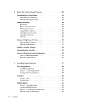
... 104 Troubleshooting USB Devices 105 Responding to a Systems Management Alert Message 105 Troubleshooting a Wet System 106 Troubleshooting a Damaged System 107 Troubleshooting System Components 107 Troubleshooting Power Supply Modules 107 Troubleshooting Fan Modules 108 Troubleshooting the DRAC/MC Module 109 Troubleshooting a Network Switch Module 110 Troubleshooting Server Module Components 110 Inside the Server...
... 104 Troubleshooting USB Devices 105 Responding to a Systems Management Alert Message 105 Troubleshooting a Wet System 106 Troubleshooting a Damaged System 107 Troubleshooting System Components 107 Troubleshooting Power Supply Modules 107 Troubleshooting Fan Modules 108 Troubleshooting the DRAC/MC Module 109 Troubleshooting a Network Switch Module 110 Troubleshooting Server Module Components 110 Inside the Server...
Hardware Owner's Manual (PDF)
Page 10
...button activates the identification indicator on both the front and back (on the KVM module) of the server modules in the chassis. The power supplies, fans, DRAC/MC, and I /O module for network connectivity. To function as an individual server encompassing up to two microprocessors, up...to turn on the system; Each server module functions as a system, a server module is inserted into a chassis that supports power supplies, fan modules, a management module (Dell™ Remote Access Controller/Modular Chassis [DRAC/MC]), a KVM switch module, and at all bays must be populated at least ...
...button activates the identification indicator on both the front and back (on the KVM module) of the server modules in the chassis. The power supplies, fans, DRAC/MC, and I /O module for network connectivity. To function as an individual server encompassing up to two microprocessors, up...to turn on the system; Each server module functions as a system, a server module is inserted into a chassis that supports power supplies, fan modules, a management module (Dell™ Remote Access Controller/Modular Chassis [DRAC/MC]), a KVM switch module, and at all bays must be populated at least ...

Hardware Owner's Manual (PDF)
Page 18
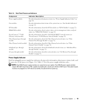
Table 1-4 provides information about the back-panel features. Back-Panel Features The back of the chassis supports four I /O bay 3 9 power supply modules (4) 12 blanks (2) 18 About Your System Back-Panel Features 1 2 3 4 12 11 5 6 4 3 10 1 I/O bay 2 4 I/O bay 1 7 KVM module 10 blanks (2) 7 2 1 8 9 2... (2) 5 Fibre Channel pass-through module 8 DRAC/MC module 11 I/O bay 4 3 PowerConnect 5316M Ethernet switch module 6 I /O module bays, the DRAC/MC, fan modules, and power supply modules. Figure 1-5 shows a sample configuration and the numbering for the bays. Figure 1-5.
Table 1-4 provides information about the back-panel features. Back-Panel Features The back of the chassis supports four I /O bay 3 9 power supply modules (4) 12 blanks (2) 18 About Your System Back-Panel Features 1 2 3 4 12 11 5 6 4 3 10 1 I/O bay 2 4 I/O bay 1 7 KVM module 10 blanks (2) 7 2 1 8 9 2... (2) 5 Fibre Channel pass-through module 8 DRAC/MC module 11 I/O bay 4 3 PowerConnect 5316M Ethernet switch module 6 I /O module bays, the DRAC/MC, fan modules, and power supply modules. Figure 1-5 shows a sample configuration and the numbering for the bays. Figure 1-5.
Hardware Owner's Manual (PDF)
Page 19
...on page 32). Provides information about the Fibre Channel network status (see "Infiniband Passthrough Module" on page 31). Table 1-5 lists the power supply indicator codes. Provides information about the network status (see "KVM Modules" on page 21). Provides information about the KVM module (see...information about status of the system fans (see "DRAC/MC Module" on page 20). Back-Panel Features and Indicators Component Power supply modules Fan modules KVM module DRAC/MC module PowerConnect™ 5316M Ethernet switch module Fibre Channel pass-through module Fibre Channel ...
...on page 32). Provides information about the Fibre Channel network status (see "Infiniband Passthrough Module" on page 31). Table 1-5 lists the power supply indicator codes. Provides information about the network status (see "KVM Modules" on page 21). Provides information about the KVM module (see...information about status of the system fans (see "DRAC/MC Module" on page 20). Back-Panel Features and Indicators Component Power supply modules Fan modules KVM module DRAC/MC module PowerConnect™ 5316M Ethernet switch module Fibre Channel pass-through module Fibre Channel ...

Hardware Owner's Manual (PDF)
Page 20
... power supply is operational. Power Supply Indicator Codes Indicator Icon DC power indicator Fault indicator Activity Indicator Green Amber AC power present indicator Green Indicator Code The power supply is in a fault condition. See "Power Supply Modules" on page 58. The fault condition can result from either a failed power supply or a failed fan within the power supply. Power Supply Indicators 1 3 2 1 fault indicator 2 AC power present indicator 3 DC power...
... power supply is operational. Power Supply Indicator Codes Indicator Icon DC power indicator Fault indicator Activity Indicator Green Amber AC power present indicator Green Indicator Code The power supply is in a fault condition. See "Power Supply Modules" on page 58. The fault condition can result from either a failed power supply or a failed fan within the power supply. Power Supply Indicators 1 3 2 1 fault indicator 2 AC power present indicator 3 DC power...

Hardware Owner's Manual (PDF)
Page 57
... - Processors - Installing System Options The procedures in this section describe how to remove and install system components and server module components, including: • Power supply modules • Fan Modules • Dell Remote Access Controller/Modular Chassis (DRAC/MC) module • KVM modules • Network switch modules • Server modules • Server module components...
... - Processors - Installing System Options The procedures in this section describe how to remove and install system components and server module components, including: • Power supply modules • Fan Modules • Dell Remote Access Controller/Modular Chassis (DRAC/MC) module • KVM modules • Network switch modules • Server modules • Server module components...
Hardware Owner's Manual (PDF)
Page 58
... purposes. Remove and replace only one power supply module fails NOTE: Depending on the power supply module release tab. NOTE: In addition to supplying power to the chassis and the server modules. System Power Guidelines The Dell Remote Access Controller/Modular Chassis (DRAC/MC) module controls the power distribution to the system, the power supply modules also have internal fans that...
... purposes. Remove and replace only one power supply module fails NOTE: Depending on the power supply module release tab. NOTE: In addition to supplying power to the chassis and the server modules. System Power Guidelines The Dell Remote Access Controller/Modular Chassis (DRAC/MC) module controls the power distribution to the system, the power supply modules also have internal fans that...

Hardware Owner's Manual (PDF)
Page 59
... module has system fan indicators on its back panel that the power-supply module handle is fully seated. Installing System Options 59 Removing and Installing a Power Supply Module 1 2 3 1 handle 2 release tab 3 power supply module Installing a Power Supply Module 1 Ensure that identify the status of each of redundant ... four system fans (two sets of its release tab snaps securely into place. 3 Plug a power cable into the chassis until its system fans. Figure 3-1. See Figure 3-1. 2 Rotate the power-supply module handle upward until it is fully down and then slide the...
... module has system fan indicators on its back panel that the power-supply module handle is fully seated. Installing System Options 59 Removing and Installing a Power Supply Module 1 2 3 1 handle 2 release tab 3 power supply module Installing a Power Supply Module 1 Ensure that identify the status of each of redundant ... four system fans (two sets of its release tab snaps securely into place. 3 Plug a power cable into the chassis until its system fans. Figure 3-1. See Figure 3-1. 2 Rotate the power-supply module handle upward until it is fully down and then slide the...

Hardware Owner's Manual (PDF)
Page 92
...Information Guide for complete information about safety precautions, working inside the system. See "Removing a DRAC/MC Module" on page 73. 3 Remove the power supply modules. See "Removing a Server Module" on page 61. 92 Installing System Options Installing a Hard Drive Into a Drive Carrier 1 2 3 1... all of the components inside the computer, and protecting against electrostatic discharge. 1 Press the system power switch to remove the system cover and access any of the server modules. Figure 3-22. See "Removing a Power Supply Module" on page 58. 4 Remove the fan modules.
...Information Guide for complete information about safety precautions, working inside the system. See "Removing a DRAC/MC Module" on page 73. 3 Remove the power supply modules. See "Removing a Server Module" on page 61. 92 Installing System Options Installing a Hard Drive Into a Drive Carrier 1 2 3 1... all of the components inside the computer, and protecting against electrostatic discharge. 1 Press the system power switch to remove the system cover and access any of the server modules. Figure 3-22. See "Removing a Power Supply Module" on page 58. 4 Remove the fan modules.

Hardware Owner's Manual (PDF)
Page 94
... the chassis, slightly lift up the securing arm. See your Product Information Guide for complete information about safety precautions, working inside the system. See "Installing a Power Supply Module" on page 10. 2 Remove the server modules nearest the system control panel. See "Installing a Fan" on page 74. 9 Press the system...
... the chassis, slightly lift up the securing arm. See your Product Information Guide for complete information about safety precautions, working inside the system. See "Installing a Power Supply Module" on page 10. 2 Remove the server modules nearest the system control panel. See "Installing a Fan" on page 74. 9 Press the system...


