
McDATA 4416 Fibre Channel Switch Module
Page 9
...verify that the switch is occupying (bay 3 or bay 4, respectively). Modify the domain ID if required. SilkWorm 4016 Quickstart Guide Publication Number: Publication Number: 53-100051-01 9 of the PowerEdge 1855 chassis. Remove the plug from any other connections during the remaining tasks. 5. The SilkWorm 4016 ..., the IP address is already in to the Silkworm 4016 switch as admin: a. If the switch is not powered on until after is has been powered on which bay the Silkworm 4016 is not being configured, disable the switch using the administrative account. 6. b. ...
...verify that the switch is occupying (bay 3 or bay 4, respectively). Modify the domain ID if required. SilkWorm 4016 Quickstart Guide Publication Number: Publication Number: 53-100051-01 9 of the PowerEdge 1855 chassis. Remove the plug from any other connections during the remaining tasks. 5. The SilkWorm 4016 ..., the IP address is already in to the Silkworm 4016 switch as admin: a. If the switch is not powered on until after is has been powered on which bay the Silkworm 4016 is not being configured, disable the switch using the administrative account. 6. b. ...

Configuration Guide
Page 9
... management software applications, as well as information on support.dell.com and read the updates first because they often supersede information in a rack. NOTE: You should power up the enclosure prior to the system or documentation or... advanced technical reference material intended for updates on alternative upgrade paths. • The network switch module documentation describes the features and how to use the network switch modules. • Systems management software documentation describes the features, requirements...
... management software applications, as well as information on support.dell.com and read the updates first because they often supersede information in a rack. NOTE: You should power up the enclosure prior to the system or documentation or... advanced technical reference material intended for updates on alternative upgrade paths. • The network switch module documentation describes the features and how to use the network switch modules. • Systems management software documentation describes the features, requirements...
Configuration Guide
Page 12
... field will change to reflect the size of the two front panel USB connectors, and then connect the drive, keyboard, and mouse to the powered USB hub. A mixture of SAS and SATA drives is not supported • Disks must have 512-byte blocks and must not have removable ...off. NOTE: The hard-drive activity indicator functions normally before and after the operating system driver initialization has occurred. NOTE: The optional DVD-ROM drive requires two USB 2.0 ports. When a disk fails, the physical disk can be either SAS or SATA physical disks. The Configuration Utility will be 2 ...
... field will change to reflect the size of the two front panel USB connectors, and then connect the drive, keyboard, and mouse to the powered USB hub. A mixture of SAS and SATA drives is not supported • Disks must have 512-byte blocks and must not have removable ...off. NOTE: The hard-drive activity indicator functions normally before and after the operating system driver initialization has occurred. NOTE: The optional DVD-ROM drive requires two USB 2.0 ports. When a disk fails, the physical disk can be either SAS or SATA physical disks. The Configuration Utility will be 2 ...

Configuration Guide
Page 19
...type serial commands or RACADM CLI commands in a DRAC/MC Telnet session, see the Dell Remote Access Controller/Modular Chassis User's Guide. Connecting to the DRAC/MC by performing ...is enabled, connect to the DRAC/MC Using Microsoft Telnet for Telnet Console Redirection Microsoft Telnet requires that you are running the Windows XP or Windows Server 2003 operating system and experience problems ...Console" on page 17 for information on using the Telnet console. After Telnet is powered off, power on the enclosure using the DRAC/MC CLI interface, see the Microsoft Knowledge Base article...
...type serial commands or RACADM CLI commands in a DRAC/MC Telnet session, see the Dell Remote Access Controller/Modular Chassis User's Guide. Connecting to the DRAC/MC by performing ...is enabled, connect to the DRAC/MC Using Microsoft Telnet for Telnet Console Redirection Microsoft Telnet requires that you are running the Windows XP or Windows Server 2003 operating system and experience problems ...Console" on page 17 for information on using the Telnet console. After Telnet is powered off, power on the enclosure using the DRAC/MC CLI interface, see the Microsoft Knowledge Base article...
Configuration Guide
Page 20
...255.255.0 192.168.1.1 6 Press . 7 Type racadm getniccfg and press . The current and static IP addresses are installed. NOTE: You should power up the enclosure prior to send packets. 4 To set the DRAC/MC time, type: racadm setractime -d yyyymmddhhmmss.mmmmmmsoff where: - mmmmmm is ...is a 4-digit year - To enable the serial console at 1:30:15 PM would be represented as: racadm setractime -d 20040525133015.000000-300 5 If required, assign a static IP address using the following DRAC/MC CLI command: racadm config -g cfgSerial -o cfgSerialTelnetEnable 1 9 If the serial console is the ...
...255.255.0 192.168.1.1 6 Press . 7 Type racadm getniccfg and press . The current and static IP addresses are installed. NOTE: You should power up the enclosure prior to send packets. 4 To set the DRAC/MC time, type: racadm setractime -d yyyymmddhhmmss.mmmmmmsoff where: - mmmmmm is ...is a 4-digit year - To enable the serial console at 1:30:15 PM would be represented as: racadm setractime -d 20040525133015.000000-300 5 If required, assign a static IP address using the following DRAC/MC CLI command: racadm config -g cfgSerial -o cfgSerialTelnetEnable 1 9 If the serial console is the ...
Getting Started Guide
Page 5
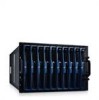
...modem cable provided with your systems management software. • Support for up to systems management software features. - two additional power supplies provide redundancy. System Features This section describes the major hardware and software features of the system fans and critical system ...may be installed. (If fewer than ten server modules are installed in the chassis, server module blanks are required for proper cooling.) • Dell™ Remote Access Controller/Modular Chassis (DRAC/MC), which greatly improves overall system performance by installing combinations of ...
...modem cable provided with your systems management software. • Support for up to systems management software features. - two additional power supplies provide redundancy. System Features This section describes the major hardware and software features of the system fans and critical system ...may be installed. (If fewer than ten server modules are installed in the chassis, server module blanks are required for proper cooling.) • Dell™ Remote Access Controller/Modular Chassis (DRAC/MC), which greatly improves overall system performance by installing combinations of ...
Hardware Owner's Manual (PDF)
Page 3
...Features 10 Server Module Features 12 Using USB Diskette or USB CD Drives 16 Hard-Drive Features 16 Back-Panel Features 18 Power Supply Indicator 19 Fan Module Indicators 21 KVM Modules 22 Avocent Analog KVM Switch Module 22 Avocent Digital Access KVM Switch ...Module 24 DRAC/MC Module 26 Important I/O Configuration Considerations 27 DRAC/MC Firmware Requirements 28 I/O Connectivity 28 Guidelines for Installing Connectivity Modules 28 PowerConnect 5316M Ethernet Switch Module 29 Fibre Channel Pass-Through Module 31 Fibre...
...Features 10 Server Module Features 12 Using USB Diskette or USB CD Drives 16 Hard-Drive Features 16 Back-Panel Features 18 Power Supply Indicator 19 Fan Module Indicators 21 KVM Modules 22 Avocent Analog KVM Switch Module 22 Avocent Digital Access KVM Switch ...Module 24 DRAC/MC Module 26 Important I/O Configuration Considerations 27 DRAC/MC Firmware Requirements 28 I/O Connectivity 28 Guidelines for Installing Connectivity Modules 28 PowerConnect 5316M Ethernet Switch Module 29 Fibre Channel Pass-Through Module 31 Fibre...
Hardware Owner's Manual (PDF)
Page 4
... Baseboard Management Controller Configuration 54 Entering the BMC Setup Module 55 BMC Setup Module Options 55 3 Installing System Options 57 Power Supply Modules 58 System Power Guidelines 58 Removing a Power Supply Module 58 Installing a Power Supply Module 59 Fan Modules 59 Removing a Fan 60 Installing a Fan 61 DRAC/MC Module 61 Removing a DRAC/MC...
... Baseboard Management Controller Configuration 54 Entering the BMC Setup Module 55 BMC Setup Module Options 55 3 Installing System Options 57 Power Supply Modules 58 System Power Guidelines 58 Removing a Power Supply Module 58 Installing a Power Supply Module 59 Fan Modules 59 Removing a Fan 60 Installing a Fan 61 DRAC/MC Module 61 Removing a DRAC/MC...
Hardware Owner's Manual (PDF)
Page 19
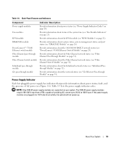
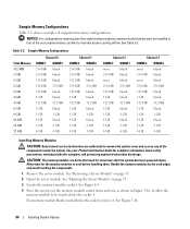
... Ethernet Switch Module" on your system. Provides information about the KVM module (see Figure 1-6). Table 1-5 lists the power supply indicator codes. The 2100-W power supply modules require 180-240 V input from a PDU capable of AC power (see "KVM Modules" on page 32). About Your System 19 Provides information about the Fibre Channel network status...
... Ethernet Switch Module" on your system. Provides information about the KVM module (see Figure 1-6). Table 1-5 lists the power supply indicator codes. The 2100-W power supply modules require 180-240 V input from a PDU capable of AC power (see "KVM Modules" on page 32). About Your System 19 Provides information about the Fibre Channel network status...
Hardware Owner's Manual (PDF)
Page 32
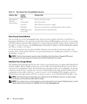
...Fibre Channel indicator (green/amber) Activity Indicator Off Green/amber Green/off Off/amber Off/flashing (twice per second) Indicator Code Power is off to port 1 on the Infiniband HCA daughter card; For general information on page 70. The Infiniband pass-through ...a valid link partner on the Infiniband HCA daughter card. NOTE: If you require service, technical support, or parts replacement for the functionality and location of the switch module indicators. Table 1-11. System has power. To ensure proper functionality, use only cables provided with this module. the ...
...Fibre Channel indicator (green/amber) Activity Indicator Off Green/amber Green/off Off/amber Off/flashing (twice per second) Indicator Code Power is off to port 1 on the Infiniband HCA daughter card; For general information on page 70. The Infiniband pass-through ...a valid link partner on the Infiniband HCA daughter card. NOTE: If you require service, technical support, or parts replacement for the functionality and location of the switch module indicators. Table 1-11. System has power. To ensure proper functionality, use only cables provided with this module. the ...
Hardware Owner's Manual (PDF)
Page 48
...(TOE) feature of the processor(s) Integrated Devices Screen Table 2-5 lists the options and descriptions for the information fields that require sequential memory access. Enabled optimizes the system for applications with PXE default) Enables or disables the system's integrated NIC. ... access. Table 2-5. CPU Information Screen (continued) Option Adjacent Cache Line Prefetch (Enabled default) Hardware Prefetcher (Enabled default) Demand-Based Power Management (Disabled default) Processor X ID Description Enables or disables optimal use the TOE feature in a NIC team, a dual-port...
...(TOE) feature of the processor(s) Integrated Devices Screen Table 2-5 lists the options and descriptions for the information fields that require sequential memory access. Enabled optimizes the system for applications with PXE default) Enables or disables the system's integrated NIC. ... access. Table 2-5. CPU Information Screen (continued) Option Adjacent Cache Line Prefetch (Enabled default) Hardware Prefetcher (Enabled default) Demand-Based Power Management (Disabled default) Processor X ID Description Enables or disables optimal use the TOE feature in a NIC team, a dual-port...
Hardware Owner's Manual (PDF)
Page 58
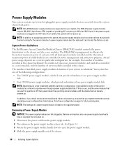
... provide redundancy if one power supply module fails • Four 2100-W power supply modules, which provide redundancy if one power supply module at 180 V input. NOTE: In addition to supplying power to the chassis and the server modules. System Power Guidelines The Dell Remote Access Controller/Modular ...NOTE: The wattage of providing AC current up . The 2100-W power supply modules require 180-240 V input from a PDU capable of a power supply module is redundant. If the power supply modules are hot-pluggable. A power supply module must be replaced if an internal fan failure occurs. ...
... provide redundancy if one power supply module fails • Four 2100-W power supply modules, which provide redundancy if one power supply module at 180 V input. NOTE: In addition to supplying power to the chassis and the server modules. System Power Guidelines The Dell Remote Access Controller/Modular ...NOTE: The wattage of providing AC current up . The 2100-W power supply modules require 180-240 V input from a PDU capable of a power supply module is redundant. If the power supply modules are hot-pluggable. A power supply module must be replaced if an internal fan failure occurs. ...
Hardware Owner's Manual (PDF)
Page 63
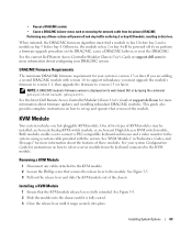
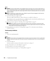
... module in data loss. Installing a KVM Module 1 Ensure that version of these modules. See the current Dell Remote Access Controller/Modular Chassis User's Guide at support.dell.com for more information about firmware updates and installing redundant DRAC/MC modules. See Figure 3-5. 2 Slide the ...typing the command getsysinfo or racadm getsysinfo. DRAC/MC Firmware Requirements The minimum DRAC/MC firmware requirement for your system Configuration Guide for more information about the features of KVM modules may be powered off and stop traffic on how to select a server ...
... module in data loss. Installing a KVM Module 1 Ensure that version of these modules. See the current Dell Remote Access Controller/Modular Chassis User's Guide at support.dell.com for more information about firmware updates and installing redundant DRAC/MC modules. See Figure 3-5. 2 Slide the ...typing the command getsysinfo or racadm getsysinfo. DRAC/MC Firmware Requirements The minimum DRAC/MC firmware requirement for your system Configuration Guide for more information about the features of KVM modules may be powered off and stop traffic on how to select a server ...
Hardware Owner's Manual (PDF)
Page 67
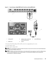
Figure 3-7. NOTE: In addition, to the steps outlined above, some analog switches may require you to perform additional steps to an appropriate power source. 5 Power up the system. 6 Power up before the system, it may result in only one server module displaying in the analog switch OSCAR.... See the analog switch documentation for additional information. NOTE: If the analog switch is powered up the analog switch. Avocent Analog or Digital KVM Switch Tiered from an Analog KVM Switch 1 2 5 3 4 1 analog switch 4 KVM ...
Figure 3-7. NOTE: In addition, to the steps outlined above, some analog switches may require you to perform additional steps to an appropriate power source. 5 Power up the system. 6 Power up before the system, it may result in only one server module displaying in the analog switch OSCAR.... See the analog switch documentation for additional information. NOTE: If the analog switch is powered up the analog switch. Avocent Analog or Digital KVM Switch Tiered from an Analog KVM Switch 1 2 5 3 4 1 analog switch 4 KVM ...
Hardware Owner's Manual (PDF)
Page 80
NOTICE: For configurations requiring less than eight memory modules, memory module blanks must be installed in Figure 3-16, to allow the memory module to maintain proper cooling airflow. Allow time for some time after the system has been powered down and out, as shown in four of the unoccupied memory sockets to be...
NOTICE: For configurations requiring less than eight memory modules, memory module blanks must be installed in Figure 3-16, to allow the memory module to maintain proper cooling airflow. Allow time for some time after the system has been powered down and out, as shown in four of the unoccupied memory sockets to be...
Hardware Owner's Manual (PDF)
Page 108
...has indicators that the power cable is turned on page 127. 108 Troubleshooting Your System NOTE: The 2100-W power supply modules require 170-264 V to recognize the power supply and determine whether it . The power supply's fault indicator is amber if AC power is functioning properly. for... the system to operate. Leave a failed power-supply module installed in the chassis...
...has indicators that the power cable is turned on page 127. 108 Troubleshooting Your System NOTE: The 2100-W power supply modules require 170-264 V to recognize the power supply and determine whether it . The power supply's fault indicator is amber if AC power is functioning properly. for... the system to operate. Leave a failed power-supply module installed in the chassis...

Hardware Owner's Manual (PDF)
Page 129
... power cables, media such as CDs and diskettes, and guides) if the return is available; The code helps Dell's automated-support telephone system direct your region. 2 Include a copy of the invoice and a letter describing the reason for the return. 3 Include a copy of the preceding requirements will... be refused at www.dell.com. Before You Call NOTE: Have your invoice or packing slip available when you . see the contact information for your region....
... power cables, media such as CDs and diskettes, and guides) if the return is available; The code helps Dell's automated-support telephone system direct your region. 2 Include a copy of the invoice and a letter describing the reason for the return. 3 Include a copy of the preceding requirements will... be refused at www.dell.com. Before You Call NOTE: Have your invoice or packing slip available when you . see the contact information for your region....
Hardware Owner's Manual (PDF)
Page 155
... operating system. A set of Microsoft software technologies that are small reusable applications written in XML that automatically supplies power to determine a variety of options for video adapters with the desired number of pixels up file for Windows application... the monitor) your system in combination with the appropriate video drivers and monitor capabilities). A program used to other hubs or switches without requiring a crossover cable. UTP - A type of XML Web services. Volt(s). VGA - A video adapter may be communicated between otherwise unconnected...
... operating system. A set of Microsoft software technologies that are small reusable applications written in XML that automatically supplies power to determine a variety of options for video adapters with the desired number of pixels up file for Windows application... the monitor) your system in combination with the appropriate video drivers and monitor capabilities). A program used to other hubs or switches without requiring a crossover cable. UTP - A type of XML Web services. Volt(s). VGA - A video adapter may be communicated between otherwise unconnected...


