

Installing a SATA Optical Drive
Page 6
...power cable routing to the power supply bays. a Route the cable through the power cable cutout in a PowerEdge 1950 Drive Tray 2 3 1 4 5 1 optical drive 3 SATA power cable 5 optical drive carrier 2 SATA cable 4 carrier latch Installing the SATA Optical Drive - NOTE: You may need to replace the existing power cable with the branching power... cable) to the SATA_A connector on the system board. c Connect the cable to the back of the chipset shroud. See Figure 1-3. PowerEdge 1950 1 Insert the optical drive tray...
...power cable routing to the power supply bays. a Route the cable through the power cable cutout in a PowerEdge 1950 Drive Tray 2 3 1 4 5 1 optical drive 3 SATA power cable 5 optical drive carrier 2 SATA cable 4 carrier latch Installing the SATA Optical Drive - NOTE: You may need to replace the existing power cable with the branching power... cable) to the SATA_A connector on the system board. c Connect the cable to the back of the chipset shroud. See Figure 1-3. PowerEdge 1950 1 Insert the optical drive tray...

Installing a SATA Optical Drive
Page 7
... Cable Routing in the PowerEdge 1950 2 1 3 4 6 5 1 SATA data cable 3 chipset shroud 5 SATA power cable 2 SATA_A connector on the system and attached peripherals. See "SAS Controller Daughter Card" in your Hardware Owner's Manual. 6 Close the system. See "Closing the System" in your Hardware Owner's Manual. 7 Reconnect the system to the power supply connector. PowerEdge 2970 or 2950...
... Cable Routing in the PowerEdge 1950 2 1 3 4 6 5 1 SATA data cable 3 chipset shroud 5 SATA power cable 2 SATA_A connector on the system and attached peripherals. See "SAS Controller Daughter Card" in your Hardware Owner's Manual. 6 Close the system. See "Closing the System" in your Hardware Owner's Manual. 7 Reconnect the system to the power supply connector. PowerEdge 2970 or 2950...

Installing a SATA Optical Drive
Page 9
... Owner's Manual. 11 Reconnect the system to an available power supply cable. 5 Replace the center fan bracket. For a PowerEdge 2900 system, connect to the power supply as follows: - For a PowerEdge 1900 system, connect to power and turn on the system backplane. For a PowerEdge 1900, use the SATA_B connector. - For a PowerEdge 2900, use the SATA_D connector. Installing the SATA Optical...
... Owner's Manual. 11 Reconnect the system to an available power supply cable. 5 Replace the center fan bracket. For a PowerEdge 2900 system, connect to the power supply as follows: - For a PowerEdge 1900 system, connect to power and turn on the system backplane. For a PowerEdge 1900, use the SATA_B connector. - For a PowerEdge 2900, use the SATA_D connector. Installing the SATA Optical...
Information Update
Page 3
PowerEdge 1950 III Systems 9 Processor Upgrades - PowerEdge 1950 II and PowerEdge 1950 III Systems 9 System Board Replacement - New System Features 5 New Performance Features 5 New High-Efficiency Power Supply and Power Monitoring Features 5 New I/O and Storage Features 6 New Security Features 6 Optional Internal USB Memory Key 6 Installing the Optional Internal USB Memory Key . . 8 Support for 8-GB Memory ...
PowerEdge 1950 III Systems 9 Processor Upgrades - PowerEdge 1950 II and PowerEdge 1950 III Systems 9 System Board Replacement - New System Features 5 New Performance Features 5 New High-Efficiency Power Supply and Power Monitoring Features 5 New I/O and Storage Features 6 New Security Features 6 Optional Internal USB Memory Key 6 Installing the Optional Internal USB Memory Key . . 8 Support for 8-GB Memory ...
Information Update
Page 5
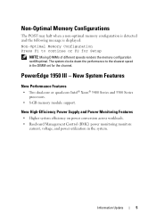
PowerEdge 1950 III - New High-Efficiency Power Supply and Power Monitoring Features • Higher system efficiency on power conversion across workloads. • Baseboard Management Control (BMC) power monitoring monitors current, voltage, and power utilization in the DIMM set for Setup NOTE: Mixing DIMMs of different speeds renders the memory configuration non6Hoptimal. The system clocks down the performance to ...
PowerEdge 1950 III - New High-Efficiency Power Supply and Power Monitoring Features • Higher system efficiency on power conversion across workloads. • Baseboard Management Control (BMC) power monitoring monitors current, voltage, and power utilization in the DIMM set for Setup NOTE: Mixing DIMMs of different speeds renders the memory configuration non6Hoptimal. The system clocks down the performance to ...
Hardware Owner's Manual (PDF)
Page 4
... Guide 50 Replacing the Plastic Fan Guide 50 Cooling Shrouds 50 System Board Cooling Shroud 50 Memory Cooling Shroud 52 Power Supplies 53 Removing a Power Supply 54 Replacing a Power Supply 55 Removing the Power Supply Blank 56 Installing the Power Supply Blank 56 SAS Controller Daughter Card 56 Removing a SAS Controller Daughter Card 56 Installing a SAS Controller Daughter Card or...
... Guide 50 Replacing the Plastic Fan Guide 50 Cooling Shrouds 50 System Board Cooling Shroud 50 Memory Cooling Shroud 52 Power Supplies 53 Removing a Power Supply 54 Replacing a Power Supply 55 Removing the Power Supply Blank 56 Installing the Power Supply Blank 56 SAS Controller Daughter Card 56 Removing a SAS Controller Daughter Card 56 Installing a SAS Controller Daughter Card or...
Hardware Owner's Manual (PDF)
Page 7
Troubleshooting the System Battery 100 Troubleshooting Power Supplies 100 Troubleshooting System Cooling Problems 101 Troubleshooting a Fan 101 Troubleshooting System Memory 102 Troubleshooting an Optical Drive 103 Troubleshooting a Hard Drive 104 Troubleshooting a SAS or ...
Troubleshooting the System Battery 100 Troubleshooting Power Supplies 100 Troubleshooting System Cooling Problems 101 Troubleshooting a Fan 101 Troubleshooting System Memory 102 Troubleshooting an Optical Drive 103 Troubleshooting a Hard Drive 104 Troubleshooting a SAS or ...

Hardware Owner's Manual (PDF)
Page 11
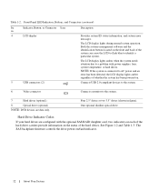
...power button 2 NMI button 3 System identification button Description The power button controls the DC power supply output to do so by qualified support personnel or by the operating system's documentation. Front-Panel LED Indicators, Buttons, and Connectors Ite Indicator, Button, or Connector Icon m 1 Power...7 Table 1-2. If the system is not running an ACPI-compliant operating system, the system performs a graceful shutdown before the power is pushed again. Used to locate a particular system within a rack. Front-Panel Features and Indicators Figure 1-1 shows the ...
...power button 2 NMI button 3 System identification button Description The power button controls the DC power supply output to do so by qualified support personnel or by the operating system's documentation. Front-Panel LED Indicators, Buttons, and Connectors Ite Indicator, Button, or Connector Icon m 1 Power...7 Table 1-2. If the system is not running an ACPI-compliant operating system, the system performs a graceful shutdown before the power is pushed again. Used to locate a particular system within a rack. Front-Panel Features and Indicators Figure 1-1 shows the ...
Hardware Owner's Manual (PDF)
Page 12
...amber when the system needs attention due to the system. 7 Hard drives (optional) 8 Optical drive (optional) NOTE: DVD devices are configured with power supplies, fans, system temperature, or hard drives. Front-Panel LED Indicators, Buttons, and Connectors (continued) Ite Indicator, Button, or Connector Icon m ...slimline optical drive Hard-Drive Indicator Codes If your hard drives are data only. The SAS backplane firmware controls the drive power-on the status of the hard-drive carriers provide information on /fault indicator. 12 About Your System Connects USB 2.0-compliant...
...amber when the system needs attention due to the system. 7 Hard drives (optional) 8 Optical drive (optional) NOTE: DVD devices are configured with power supplies, fans, system temperature, or hard drives. Front-Panel LED Indicators, Buttons, and Connectors (continued) Ite Indicator, Button, or Connector Icon m ...slimline optical drive Hard-Drive Indicator Codes If your hard drives are data only. The SAS backplane firmware controls the drive power-on the status of the hard-drive carriers provide information on /fault indicator. 12 About Your System Connects USB 2.0-compliant...

Hardware Owner's Manual (PDF)
Page 14
...'s back panel. Figure 1-3. Back-Panel Features and Indicators 1 2 3 45 6 7 8 13 12 11 10 9 1 remote access controller (optional) 4 USB connectors (2) 7 power supply 1 1 system identification button 0 1 center PCI expansion slot 3 (slot 1) 2 serial connector 5 NIC1 connector 8 power supply 2 (optional) 11 system status indicator connector 3 video connector 6 NIC2 connector 9 system status indicator 12 left PCI expansion slot (slot...
...'s back panel. Figure 1-3. Back-Panel Features and Indicators 1 2 3 45 6 7 8 13 12 11 10 9 1 remote access controller (optional) 4 USB connectors (2) 7 power supply 1 1 system identification button 0 1 center PCI expansion slot 3 (slot 1) 2 serial connector 5 NIC1 connector 8 power supply 2 (optional) 11 system status indicator connector 3 video connector 6 NIC2 connector 9 system status indicator 12 left PCI expansion slot (slot...
Hardware Owner's Manual (PDF)
Page 15
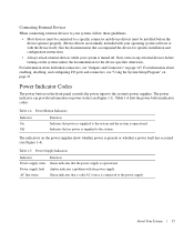
... devices must be connected to a specific connector and device drivers must be installed before turning on the power supplies show whether power is operational. Table 1-4. Power supply fault Amber indicates a problem with the device itself.) See the documentation that accompanied the device for the... before the device operates properly. (Device drivers are normally included with your operating system software or with the power supply. The indicators on the system (unless the documentation for specific installation and configuration instructions. • Always attach external devices...
... devices must be connected to a specific connector and device drivers must be installed before turning on the power supplies show whether power is operational. Table 1-4. Power supply fault Amber indicates a problem with the device itself.) See the documentation that accompanied the device for the... before the device operates properly. (Device drivers are normally included with your operating system software or with the power supply. The indicators on the system (unless the documentation for specific installation and configuration instructions. • Always attach external devices...

Hardware Owner's Manual (PDF)
Page 16
Figure 1-4. Power Supply Indicators 1 2 3 1 power supply status indicator 2 power supply fault indicator 3 AC line status indicator NIC Indicator Codes Each NIC on the back panel has an indicator that provides information on the network. See ...
Figure 1-4. Power Supply Indicators 1 2 3 1 power supply status indicator 2 power supply fault indicator 3 AC line status indicator NIC Indicator Codes Each NIC on the back panel has an indicator that provides information on the network. See ...
Hardware Owner's Manual (PDF)
Page 19
... "Troubleshooting the bad, and the system is in a configuration unsupported by Dell. processor protocol error. processor bus parity error. machine check error. See "Troubleshooting Power Supplies" on page 125. Check the AC power source for the specified power supply. If the problem persists, see "Troubleshooting Power Supplies" on page 100. unsupported configuration. CPU Init The system BIOS has...
... "Troubleshooting the bad, and the system is in a configuration unsupported by Dell. processor protocol error. processor bus parity error. machine check error. See "Troubleshooting Power Supplies" on page 125. Check the AC power source for the specified power supply. If the problem persists, see "Troubleshooting Power Supplies" on page 100. unsupported configuration. CPU Init The system BIOS has...
Hardware Owner's Manual (PDF)
Page 20
...board is faulty. See "Getting Help" on page 100. The system BIOS has reported a PCIe fatal error on page 125. If the last supply Supplies" on page 125. PCI PERR B## D## F## PCI PERR Slot # The system BIOS has reported a PCI parity error on a component that ..."Troubleshooting Expansion Cards" on page 125. LCD Status Messages (continued) Code E1624 E1710 E1711 E1712 E1714 E171F Text Causes Corrective Actions PS Redundancy The power supply subsystem is faulty. PCIE Fatal Err B## D## F## PCIE Fatal Err Slot # The system BIOS has reported a PCIe fatal error on a component ...
...board is faulty. See "Getting Help" on page 100. The system BIOS has reported a PCIe fatal error on page 125. If the last supply Supplies" on page 125. PCI PERR B## D## F## PCI PERR Slot # The system BIOS has reported a PCI parity error on a component that ..."Troubleshooting Expansion Cards" on page 125. LCD Status Messages (continued) Code E1624 E1710 E1711 E1712 E1714 E171F Text Causes Corrective Actions PS Redundancy The power supply subsystem is faulty. PCIE Fatal Err B## D## F## PCIE Fatal Err Slot # The system BIOS has reported a PCIe fatal error on a component ...
Hardware Owner's Manual (PDF)
Page 24
... a very precise fault condition that the problem is unable to the normal state. events. Solving Problems Described by deleting event and is a failing power supply. For example, if you receive a series of Battery" on , the LCD message is recorded from the display: • Clear the SEL ...- For other faults, you might determine that is removed from the electrical outlet; wait approximately ten seconds, reconnect the power cable, and restart the system. See "RAID battery has less than 24 hours of messages indicating multiple voltage faults, you might be able...
... a very precise fault condition that the problem is unable to the normal state. events. Solving Problems Described by deleting event and is a failing power supply. For example, if you receive a series of Battery" on , the LCD message is recorded from the display: • Clear the SEL ...- For other faults, you might determine that is removed from the electrical outlet; wait approximately ten seconds, reconnect the power cable, and restart the system. See "RAID battery has less than 24 hours of messages indicating multiple voltage faults, you might be able...
Hardware Owner's Manual (PDF)
Page 43
Installing System Components This section describes how to install the following system components: • Cooling fan modules • Cooling shrouds • Power supplies • SAS controller daughter card or SAS RAID controller daughter card • RAID battery • RAID controller expansion card • Expansion cards • Boot drive &#...
Installing System Components This section describes how to install the following system components: • Cooling fan modules • Cooling shrouds • Power supplies • SAS controller daughter card or SAS RAID controller daughter card • RAID battery • RAID controller expansion card • Expansion cards • Boot drive &#...
Hardware Owner's Manual (PDF)
Page 45
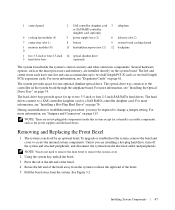
... end of the bezel. 5 Pull the bezel away from the electrical outlet and peripherals. Several hardware options, such as the power supplies and the hard drives. 1 control panel 2 SAS controller daughter card 3 sideplane or SAS RAID controller daughter card (optional) 4 cooling fan modules... (4) 5 power supply bays (2) 6 left end of the bezel away from the system to two half-length PCI-X cards or two half-length PCIe expansion cards...
... end of the bezel. 5 Pull the bezel away from the electrical outlet and peripherals. Several hardware options, such as the power supplies and the hard drives. 1 control panel 2 SAS controller daughter card 3 sideplane or SAS RAID controller daughter card (optional) 4 cooling fan modules... (4) 5 power supply bays (2) 6 left end of the bezel away from the system to two half-length PCI-X cards or two half-length PCIe expansion cards...

Hardware Owner's Manual (PDF)
Page 53
... down onto the system, directly over the memory modules and the processors. 2 Using the interior system board cooling shroud as a redundant, hot-plug power source. See "Installing the Power Supply Blank" on page 56. Memory Cooling Shroud 1 2 3 4 1 memory cooling shroud 4 system processors (2) 2 memory shroud release tab 3 memory modules (8) Replacing the Memory Cooling Shroud...
... down onto the system, directly over the memory modules and the processors. 2 Using the interior system board cooling shroud as a redundant, hot-plug power source. See "Installing the Power Supply Blank" on page 56. Memory Cooling Shroud 1 2 3 4 1 memory cooling shroud 4 system processors (2) 2 memory shroud release tab 3 memory modules (8) Replacing the Memory Cooling Shroud...

Hardware Owner's Manual (PDF)
Page 54
... be installed in the left side of the power supply by pressing in toward the right until the power supply is in the redundant mode when two power supplies are installed and both power supplies are installed, the second power supply serves as a redundant, hot-plug power source. Removing a Power Supply NOTICE: The system requires one power supply for extended periods of 120 to 220...
... be installed in the left side of the power supply by pressing in toward the right until the power supply is in the redundant mode when two power supplies are installed and both power supplies are installed, the second power supply serves as a redundant, hot-plug power source. Removing a Power Supply NOTICE: The system requires one power supply for extended periods of 120 to 220...

Hardware Owner's Manual (PDF)
Page 55
... Components 55 See "Removing a Power Supply" on page 54. 2 Holding the power-supply handle, slide the new power supply into a power outlet. For information about the power cable retention bracket, see Figure 1-4). Removing and Installing a Power Supply 1 2 3 4 5 7 6 1 power-supply 4 power supply blank 7 locking tab 2 power-supply handle 3 cable retention bracket 5 power-supply bay 2 (optional) 6 redundant power supply bay 1 Replacing a Power Supply 1 If you may need to recognize the power supply and determine its status...
... Components 55 See "Removing a Power Supply" on page 54. 2 Holding the power-supply handle, slide the new power supply into a power outlet. For information about the power cable retention bracket, see Figure 1-4). Removing and Installing a Power Supply 1 2 3 4 5 7 6 1 power-supply 4 power supply blank 7 locking tab 2 power-supply handle 3 cable retention bracket 5 power-supply bay 2 (optional) 6 redundant power supply bay 1 Replacing a Power Supply 1 If you may need to recognize the power supply and determine its status...


