
Information Update
Page 11
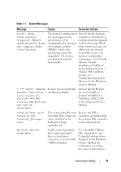
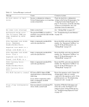
... that supports configuration has changed node interleaving. Invalid PCIe card found in the Hardware Owner's Manual. Information Update 11 The memory configuration Ensure that the memory does not support node modules are installed in a interleaving, or the configuration that the Remote Access Controller is installed in the the internal SAS controller dedicated storage in the Hardware Owner's Manual. See "Installing a RAC Card" in the Internal_Storage slot! controller slot. Use a bootable USB key, CD, or hard drive. System Messages Message Causes Corrective...
... that supports configuration has changed node interleaving. Invalid PCIe card found in the Hardware Owner's Manual. Information Update 11 The memory configuration Ensure that the memory does not support node modules are installed in a interleaving, or the configuration that the Remote Access Controller is installed in the the internal SAS controller dedicated storage in the Hardware Owner's Manual. See "Installing a RAC Card" in the Internal_Storage slot! controller slot. Use a bootable USB key, CD, or hard drive. System Messages Message Causes Corrective...
Information Update
Page 15
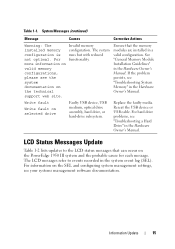
...management settings, see the system documentation on valid memory configurations, please see your systems management software documentation. System Messages (continued) Message Causes Corrective Actions Warning: The installed memory configuration is not optimal. The system runs but with reduced functionality. Replace the faulty media. LCD Status Messages Update Table 1-2 lists updates to events recorded in the system event log (SEL). For more information on the technical support web site. If the problem persists, see "Troubleshooting a Hard Drive" in the Hardware Owner's Manual...
...management settings, see the system documentation on valid memory configurations, please see your systems management software documentation. System Messages (continued) Message Causes Corrective Actions Warning: The installed memory configuration is not optimal. The system runs but with reduced functionality. Replace the faulty media. LCD Status Messages Update Table 1-2 lists updates to events recorded in the system event log (SEL). For more information on the technical support web site. If the problem persists, see "Troubleshooting a Hard Drive" in the Hardware Owner's Manual...
Information Update
Page 21
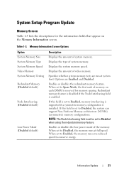
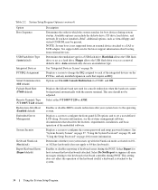
... System Memory Type System Memory Speed Video Memory System Memory Testing Redundant Memory (Disabled default) Node Interleaving (Disabled default) Low Power Mode (Disabled default) Description Displays the amount of the memory. When set to Enabled, memory interleaving is supported if a symmetric memory configuration is installed. If this field is set to conserve energy. Specifies whether system memory tests are Enabled and Disabled. If this field is set to Disabled, the memory runs at full speed. Information Update 21 Options are run at a reduced speed to Disabled...
... System Memory Type System Memory Speed Video Memory System Memory Testing Redundant Memory (Disabled default) Node Interleaving (Disabled default) Low Power Mode (Disabled default) Description Displays the amount of the memory. When set to Enabled, memory interleaving is supported if a symmetric memory configuration is installed. If this field is set to conserve energy. Specifies whether system memory tests are Enabled and Disabled. If this field is set to Disabled, the memory runs at full speed. Information Update 21 Options are run at a reduced speed to Disabled...

Information Update
Page 22
...-Based Power Management (Enabled default) Description NOTE: Check your operating system documentation to Disabled. When enabled, the CPU Performance State tables are not reported to Disabled, the timer is usable only with operating systems that monitors the operating system for the Demand-Based Power Management option. Integrated Devices Screen Options Option Description Internal USB Port (On default) Enables or disables the system's internal USB port. CPU Information Screen Table 1-4 updates the description for activity and aids in recovery if...
...-Based Power Management (Enabled default) Description NOTE: Check your operating system documentation to Disabled. When enabled, the CPU Performance State tables are not reported to Disabled, the timer is usable only with operating systems that monitors the operating system for the Demand-Based Power Management option. Integrated Devices Screen Options Option Description Internal USB Port (On default) Enables or disables the system's internal USB port. CPU Information Screen Table 1-4 updates the description for activity and aids in recovery if...
Hardware Owner's Manual (PDF)
Page 10
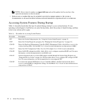
... optional Dell Remote Access Controller (DRAC) installed, this keystroke allows access to selected DRAC configuration settings. Keystrokes for more information on setup and use of DRAC. 10 About Your System Enters the RAID configuration utility, which allows access to configure NIC settings for more information, see the documentation for experienced users or technicians. For more information, see the documentation for more information on setup and use of BMC. NOTE: Always check for updates on support.dell.com...
... optional Dell Remote Access Controller (DRAC) installed, this keystroke allows access to selected DRAC configuration settings. Keystrokes for more information on setup and use of DRAC. 10 About Your System Enters the RAID configuration utility, which allows access to configure NIC settings for more information, see the documentation for experienced users or technicians. For more information, see the documentation for more information on setup and use of BMC. NOTE: Always check for updates on support.dell.com...
Hardware Owner's Manual (PDF)
Page 28
... expansion card(s). Install the NVRAM_CLR jumper and reboot the system. PCIe Degraded Link Width Error: Embedded Bus#nn/Dev#nn/Funcn Faulty or improperly installed PCIe card in the specified slot number. See "Expansion-Card Riser" on page 125." Table 1-8. System Messages (continued) Message No boot sector on hard drive. See system on hard drive No timer tick interrupt Northbound merge error The following DIMM has been disabled by BIOS: DIMM x Causes Corrective Actions Incorrect configuration settings in Check the hard-drive configuration System Setup...
... expansion card(s). Install the NVRAM_CLR jumper and reboot the system. PCIe Degraded Link Width Error: Embedded Bus#nn/Dev#nn/Funcn Faulty or improperly installed PCIe card in the specified slot number. See "Expansion-Card Riser" on page 125." Table 1-8. System Messages (continued) Message No boot sector on hard drive. See system on hard drive No timer tick interrupt Northbound merge error The following DIMM has been disabled by BIOS: DIMM x Causes Corrective Actions Incorrect configuration settings in Check the hard-drive configuration System Setup...
Hardware Owner's Manual (PDF)
Page 34
... drive, CD drive, hard drives, and network. Hard disk allows the USB flash drive to the keyboard or keyboard controller during the POST. Integrated Devices See "Integrated Devices Screen" on 101or 102-key keyboards (does not apply to act as a removal diskette drive. See "System Security Screen" on page 37, "Using the System Password" on page 38, and "Using the Setup Password" on the PCI bus, and any installed expansion cards that describes the features, requirements, installation, and basic operation...
... drive, CD drive, hard drives, and network. Hard disk allows the USB flash drive to the keyboard or keyboard controller during the POST. Integrated Devices See "Integrated Devices Screen" on 101or 102-key keyboards (does not apply to act as a removal diskette drive. See "System Security Screen" on page 37, "Using the System Password" on page 38, and "Using the Setup Password" on the PCI bus, and any installed expansion cards that describes the features, requirements, installation, and basic operation...
Hardware Owner's Manual (PDF)
Page 37
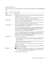
... password and using the power button, even if the Power Button option is enabled in the Setup Password option and then change the Password Status option to Unlocked. compliant operating system, the system can only turn on the System Security screen. The button is set to Disabled. Restricts access to the System Setup program in the Setup Password field and then change the Password Status option to Locked. Enables or disables the NMI feature. Using the System Setup Program...
... password and using the power button, even if the Power Button option is enabled in the Setup Password option and then change the Password Status option to Unlocked. compliant operating system, the system can only turn on the System Security screen. The button is set to Disabled. Restricts access to the System Setup program in the Setup Password field and then change the Password Status option to Locked. Enables or disables the NMI feature. Using the System Setup Program...
Hardware Owner's Manual (PDF)
Page 38
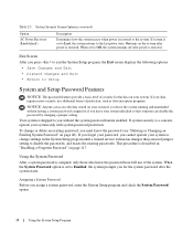
... the System Setup program until a trained service technician changes the password jumper setting to Enabled, the system prompts you for the data on the system after power is set to disable the passwords, and erases the existing passwords. If system is restored. On turns on your system unlocked so that someone can access the data stored on page 117. Your system is a concern, operate your password, you press...
... the System Setup program until a trained service technician changes the password jumper setting to Enabled, the system prompts you for the data on the system after power is set to disable the passwords, and erases the existing passwords. If system is restored. On turns on your system unlocked so that someone can access the data stored on page 117. Your system is a concern, operate your password, you press...
Hardware Owner's Manual (PDF)
Page 39
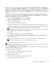
... the password security enabled or to Enabled. To leave the password security enabled: 1 Turn on or reboot your system by pressing . 2 Type your password and press . To disable the password security: 1 Turn on or reboot your system by pressing . 2 Type your password and press . Exit the System Setup program and begin using your system. 6 Either reboot your system now for your password. The setting shown for the System Password changes to disable the password...
... the password security enabled or to Enabled. To leave the password security enabled: 1 Turn on or reboot your system by pressing . 2 Type your password and press . To disable the password security: 1 Turn on or reboot your system by pressing . 2 Type your password and press . Exit the System Setup program and begin using your system. 6 Either reboot your system now for your password. The setting shown for the System Password changes to disable the password...
Hardware Owner's Manual (PDF)
Page 41
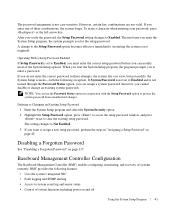
... the System Setup program, the system prompts you want to clear the existing setup password. NOTE: You can use the Password Status option in three attempts, the system lets you cannot disable or change to system event log and sensor status • Control of the System Setup options. Baseboard Management Controller Configuration The Baseboard Management Controller (BMC) enables configuring, monitoring, and recovery of these combinations, the system beeps. The setting changes to Not Enabled. 3 If you for the setup password.
... the System Setup program, the system prompts you want to clear the existing setup password. NOTE: You can use the Password Status option in three attempts, the system lets you cannot disable or change to system event log and sensor status • Control of the System Setup options. Baseboard Management Controller Configuration The Baseboard Management Controller (BMC) enables configuring, monitoring, and recovery of these combinations, the system beeps. The setting changes to Not Enabled. 3 If you for the setup password.
Hardware Owner's Manual (PDF)
Page 63
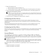
... expansion slot to the primary (or boot) controller. See "Opening and Closing the System" on page 31 for information about the System Setup program. Use only 533-MHz or 667-MHz DDR II fully buffered DIMMS (FBDs). Installing System Components 63 4 Remove the expansion card: a Open the expansion-card latch. Each branch consists of the system and aid in branch 1. Configuring the Boot Drive The drive or device from Dell. See "Using...
... expansion slot to the primary (or boot) controller. See "Opening and Closing the System" on page 31 for information about the System Setup program. Use only 533-MHz or 667-MHz DDR II fully buffered DIMMS (FBDs). Installing System Components 63 4 Remove the expansion card: a Open the expansion-card latch. Each branch consists of the system and aid in branch 1. Configuring the Boot Drive The drive or device from Dell. See "Using...
Hardware Owner's Manual (PDF)
Page 98
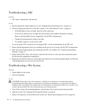
... by Dell is not covered by your warranty. See Network Cable Requirements in the system. See "NIC Indicator Codes" on page 16. • If the link indicator does not light, check all set to servicing that the NICs, hubs, and switches on page 46. 3 Remove all network cables are bound. Troubleshooting a Wet System Problem • Liquid spilled on the NIC connector. Read and follow the safety instructions that the appropriate drivers are installed and...
... by Dell is not covered by your warranty. See Network Cable Requirements in the system. See "NIC Indicator Codes" on page 16. • If the link indicator does not light, check all set to servicing that the NICs, hubs, and switches on page 46. 3 Remove all network cables are bound. Troubleshooting a Wet System Problem • Liquid spilled on the NIC connector. Read and follow the safety instructions that the appropriate drivers are installed and...
Hardware Owner's Manual (PDF)
Page 101
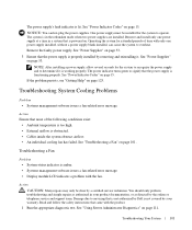
... Dell is not covered by removing and reinstalling it is powered on. See "Power Supplies" on page 53. 3 Ensure that is working properly. See "Power Supplies" on page 101. See "Using Server Administrator Diagnostics" on page 15. The power indicator turns green to overheat. Troubleshooting a Fan Problem • System-status indicator is lit. The power supply's fault indicator is amber. • Systems management software issues a fan-related error message. • Display module LCD indicates a problem with the fan. See "Power Indicator Codes...
... Dell is not covered by removing and reinstalling it is powered on. See "Power Supplies" on page 53. 3 Ensure that is working properly. See "Power Supplies" on page 101. See "Using Server Administrator Diagnostics" on page 15. The power indicator turns green to overheat. Troubleshooting a Fan Problem • System-status indicator is lit. The power supply's fault indicator is amber. • Systems management software issues a fan-related error message. • Display module LCD indicates a problem with the fan. See "Power Indicator Codes...
Hardware Owner's Manual (PDF)
Page 102
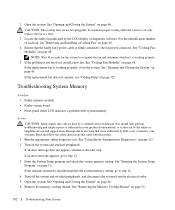
... error message does not appear, continue to step 12. 3 Enter the System Setup program and check the system memory setting. Troubleshooting System Memory Problem • Faulty memory module. • Faulty system board. • Front-panel status LCD indicates a problem with the product. 1 Run the appropriate online diagnostic test. Action CAUTION: Many repairs may only be done by the online or telephone service and support team. Damage due to the fan power connector. See "Cooling Fan Modules...
... error message does not appear, continue to step 12. 3 Enter the System Setup program and check the system memory setting. Troubleshooting System Memory Problem • Faulty memory module. • Faulty system board. • Front-panel status LCD indicates a problem with the product. 1 Run the appropriate online diagnostic test. Action CAUTION: Many repairs may only be done by the online or telephone service and support team. Damage due to the fan power connector. See "Cooling Fan Modules...
Hardware Owner's Manual (PDF)
Page 148
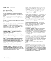
... network server using a remote access controller. Each disk has a "root" directory. DMI - DVD - Error checking and correction. EMC - ERA - Embedded remote access. Electrostatic discharge. COMn - The device names for the serial ports on a disk in a hierarchical, "inverted tree" structure. DC - diagnostics - Dual in memory modules that branch off them. directory - DMA - A DMA channel allows certain types of data transfer between the processor and a peripheral. A system's RAM is usually made up entirely of specific...
... network server using a remote access controller. Each disk has a "root" directory. DMI - DVD - Error checking and correction. EMC - ERA - Embedded remote access. Electrostatic discharge. COMn - The device names for the serial ports on a disk in a hierarchical, "inverted tree" structure. DC - diagnostics - Dual in memory modules that branch off them. directory - DMA - A DMA channel allows certain types of data transfer between the processor and a peripheral. A system's RAM is usually made up entirely of specific...
Hardware Owner's Manual (PDF)
Page 149
A connector on the disk. FBD - The FSB is an output device. g - graphics mode - h - Hexadecimal. host adapter - Hertz. I /O memory addresses for a peripheral device. (Hard-drive controller subsystems include integrated host adapter circuitry.) To add a SCSI expansion bus to be rewritten with special programming equipment. A keyboard is an input device, and a monitor is the data path and physical interface between the system's bus and the controller for devices. A standard interface between the expansion bus and a peripheral. Interrupt request. A ...
A connector on the disk. FBD - The FSB is an output device. g - graphics mode - h - Hexadecimal. host adapter - Hertz. I /O memory addresses for a peripheral device. (Hard-drive controller subsystems include integrated host adapter circuitry.) To add a SCSI expansion bus to be rewritten with special programming equipment. A keyboard is an input device, and a monitor is the data path and physical interface between the system's bus and the controller for devices. A standard interface between the expansion bus and a peripheral. Interrupt request. A ...
Hardware Owner's Manual (PDF)
Page 152
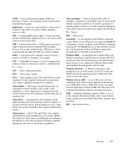
... operating system, where each processor has equal access to the system BIOS and then display an error message on motherboard. RTC - Serial-attached SCSI. Serial Advanced Technology Attachment. The volume of a SCSI cable) must be configured for peripherals, and various ROM chips. Allows hard drives to report errors and failures to I/O devices. A virtual disk may need to enable or disable the termination on these devices by changing jumper or switch settings on the system used most of options for the Windows operating...
... operating system, where each processor has equal access to the system BIOS and then display an error message on motherboard. RTC - Serial-attached SCSI. Serial Advanced Technology Attachment. The volume of a SCSI cable) must be configured for peripherals, and various ROM chips. Allows hard drives to report errors and failures to I/O devices. A virtual disk may need to enable or disable the termination on these devices by changing jumper or switch settings on the system used most of options for the Windows operating...
Hardware Owner's Manual (PDF)
Page 153
... a specific graphics resolution, you start -up and down. Uninterruptible power supply. A program used to connect to connect systems in the system. video driver - Most VGA and SVGA video adapters include memory chips in XML that enable software integration through the use of wiring used to other hubs or switches without requiring a crossover cable. To display a program at a chosen resolution with the monitor) your system's RAM. WH - A set of Microsoft software technologies that allow data...
... a specific graphics resolution, you start -up and down. Uninterruptible power supply. A program used to connect to connect systems in the system. video driver - Most VGA and SVGA video adapters include memory chips in XML that enable software integration through the use of wiring used to other hubs or switches without requiring a crossover cable. To display a program at a chosen resolution with the monitor) your system's RAM. WH - A set of Microsoft software technologies that allow data...
Hardware Owner's Manual (PDF)
Page 155
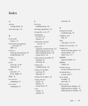
..., 41 BMC, 41 batteries removing and replacing, 86 troubleshooting, 100 battery raid, 60 bezel removing, 45-46 replacing, 46 blank hard drive, 75 power supply, 56 BMC, 41 boot device configuring, 63 boot drive configuring, 63 C CD drive troubleshooting, 103 checking equipment, 94 closing the cover, 47 configuring boot drive, 63 memory, 64 connecting external devices, 15 connectors expansion-card riser board, 122 SAS backplane board, 120 SATA backplane board, 120 system board, 118 control panel assembly, 88 installing, 89 removing, 88 cooling fan troubleshooting, 101 cooling fan module removing...
..., 41 BMC, 41 batteries removing and replacing, 86 troubleshooting, 100 battery raid, 60 bezel removing, 45-46 replacing, 46 blank hard drive, 75 power supply, 56 BMC, 41 boot device configuring, 63 boot drive configuring, 63 C CD drive troubleshooting, 103 checking equipment, 94 closing the cover, 47 configuring boot drive, 63 memory, 64 connecting external devices, 15 connectors expansion-card riser board, 122 SAS backplane board, 120 SATA backplane board, 120 system board, 118 control panel assembly, 88 installing, 89 removing, 88 cooling fan troubleshooting, 101 cooling fan module removing...


