
Information Update
Page 3
... High-Efficiency Power Supply and Power Monitoring Features 5 New I/O and Storage Features 6 New Security Features 6 Optional Internal USB Memory Key 6 Installing the Optional Internal USB Memory Key . . 8 Support for 8-GB Memory Modules - PowerEdge 1950 II and PowerEdge 1950 III Systems 9 System Board Replacement - Safeguarding Encrypted Data 10 System Message Update 10 LCD Status Messages Update 15 Contents 3
... High-Efficiency Power Supply and Power Monitoring Features 5 New I/O and Storage Features 6 New Security Features 6 Optional Internal USB Memory Key 6 Installing the Optional Internal USB Memory Key . . 8 Support for 8-GB Memory Modules - PowerEdge 1950 II and PowerEdge 1950 III Systems 9 System Board Replacement - Safeguarding Encrypted Data 10 System Message Update 10 LCD Status Messages Update 15 Contents 3
Information Update
Page 4
Incorrect Processor Information 25 System Support for Microsoft Windows 2000 . . . 25 Hardware Owner's Manual Updates 26 Installing the Processor 26 System Diagnostics Custom Test Options . . . . . 26 4 Contents System Setup Program Update 21 Memory Screen 21 CPU Information Screen 22 Integrated Devices Screen 22 System Security Screen 23 Operating System Information 25 Enumeration of NICs 25 RHEL -
Incorrect Processor Information 25 System Support for Microsoft Windows 2000 . . . 25 Hardware Owner's Manual Updates 26 Installing the Processor 26 System Diagnostics Custom Test Options . . . . . 26 4 Contents System Setup Program Update 21 Memory Screen 21 CPU Information Screen 22 Integrated Devices Screen 22 System Security Screen 23 Operating System Information 25 Enumeration of NICs 25 RHEL -
Information Update
Page 5
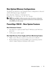
... is detected and the following message is displayed: Non-Optimal Memory Configuration Press F1 to the slowest speed in the system. The system clocks down the performance to continue or F2 for the channel. PowerEdge 1950 III - New High-Efficiency Power Supply and Power Monitoring Features • Higher system efficiency on power conversion...
... is detected and the following message is displayed: Non-Optimal Memory Configuration Press F1 to the slowest speed in the system. The system clocks down the performance to continue or F2 for the channel. PowerEdge 1950 III - New High-Efficiency Power Supply and Power Monitoring Features • Higher system efficiency on power conversion...
Information Update
Page 6
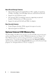
... cards. • One internal USB 2.0-compliant connector supporting an optional bootable USB flash drive or USB memory key. • Support for iSCSI boot. To use with a USB flash memory key (see Figure 1-1). Optional Internal USB Memory Key The PowerEdge 1950 III system provides an internal USB connector located on page 22. 6 Information Update See "Integrated...
... cards. • One internal USB 2.0-compliant connector supporting an optional bootable USB flash drive or USB memory key. • Support for iSCSI boot. To use with a USB flash memory key (see Figure 1-1). Optional Internal USB Memory Key The PowerEdge 1950 III system provides an internal USB connector located on page 22. 6 Information Update See "Integrated...
Information Update
Page 7
... Setup program. Internal USB Connector Location 1 2 1 system board 2 internal USB connector location To boot from the USB memory key, you must configure the USB memory key with components inside the system, the USB key must be formatted using the format utility provided by the key manufacturer.... NOTE: USB keys that accompanied the USB memory key. NOTE: To avoid interference with a boot image and then specify the USB memory key in the boot sequence in the Hardware Owner's Manual. For information on creating a bootable...
... Setup program. Internal USB Connector Location 1 2 1 system board 2 internal USB connector location To boot from the USB memory key, you must configure the USB memory key with components inside the system, the USB key must be formatted using the format utility provided by the key manufacturer.... NOTE: USB keys that accompanied the USB memory key. NOTE: To avoid interference with a boot image and then specify the USB memory key in the boot sequence in the Hardware Owner's Manual. For information on creating a bootable...
Information Update
Page 8
...connector on the system board and insert the USB memory key into the USB connector. See "Removing the Memory Cooling Shroud" in the Hardware Owner's Manual. 3 Remove the memory cooling shroud. Installing an Internal USB Key 1 2 1 USB memory key 2 internal USB connector 8 Information Update See... Product Information Guide for complete information about safety precautions, working inside the system. Figure 1-2. Installing the Optional Internal USB Memory Key WARNING: Only trained service technicians are authorized to remove the system cover and access any of the components inside the...
...connector on the system board and insert the USB memory key into the USB connector. See "Removing the Memory Cooling Shroud" in the Hardware Owner's Manual. 3 Remove the memory cooling shroud. Installing an Internal USB Key 1 2 1 USB memory key 2 internal USB connector 8 Information Update See... Product Information Guide for complete information about safety precautions, working inside the system. Figure 1-2. Installing the Optional Internal USB Memory Key WARNING: Only trained service technicians are authorized to remove the system cover and access any of the components inside the...
Information Update
Page 9
...during POST. NOTE: Prior to upgrading your system, verify that your system is on your system. Processor Upgrades - See support.dell.com for your system. Loading the latest BIOS version ensures that the latest system BIOS version is fully supported. See "Using ...5100 and 5200 series of dual-core Intel Xeon processors and the 5300 and 5400 series of physical memory. PowerEdge 1950 III Systems PowerEdge 1950 III systems have added support for 8-GB Memory Modules - 5 Replace the memory cooling shroud. 6 Close the system. See "Closing the System" in the Hardware Owner's Manual...
...during POST. NOTE: Prior to upgrading your system, verify that your system is on your system. Processor Upgrades - See support.dell.com for your system. Loading the latest BIOS version ensures that the latest system BIOS version is fully supported. See "Using ...5100 and 5200 series of dual-core Intel Xeon processors and the 5300 and 5400 series of physical memory. PowerEdge 1950 III Systems PowerEdge 1950 III systems have added support for 8-GB Memory Modules - 5 Replace the memory cooling shroud. 6 Close the system. See "Closing the System" in the Hardware Owner's Manual...
Information Update
Page 11
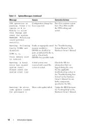
...The system halted because Remove the PCIe an invalid PCIe expansion expansion card and install card is properly installed. controller slot. Memory configuration does not support Node Interleaving. No boot device available Faulty or missing optical drive subsystem, hard drive, or hard-drive... in the Hardware Owner's Manual for DIMM) so that node additional information interleaving cannot be available... The memory configuration Ensure that the memory does not support node modules are installed in a interleaving, or the configuration that the Remote Access Controller ...
...The system halted because Remove the PCIe an invalid PCIe expansion expansion card and install card is properly installed. controller slot. Memory configuration does not support Node Interleaving. No boot device available Faulty or missing optical drive subsystem, hard drive, or hard-drive... in the Hardware Owner's Manual for DIMM) so that node additional information interleaving cannot be available... The memory configuration Ensure that the memory does not support node modules are installed in a interleaving, or the configuration that the Remote Access Controller ...
Information Update
Page 14
...Check the SEL for a possible fault. Update the BIOS firmware. Configuration change and reset the system. Faulty or improperly seated See "Troubleshooting memory module(s). Warning! Warning: A fatal error has caused system reset! for processor n Hardware Owner's Manual. 14 Information Update Warning: Following ...are disabled in the for any faulty components specified in the Hardware Owner's Manual. Table 1-1. System Memory" in the DIMMs are disabled: DIMM n1 n2 Total memory size is pending. pairs, as indicated by the n1 and n2. No micro Micro code update failed...
...Check the SEL for a possible fault. Update the BIOS firmware. Configuration change and reset the system. Faulty or improperly seated See "Troubleshooting memory module(s). Warning! Warning: A fatal error has caused system reset! for processor n Hardware Owner's Manual. 14 Information Update Warning: Following ...are disabled in the for any faulty components specified in the Hardware Owner's Manual. Table 1-1. System Memory" in the DIMMs are disabled: DIMM n1 n2 Total memory size is pending. pairs, as indicated by the n1 and n2. No micro Micro code update failed...
Information Update
Page 15
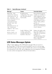
The system runs but with reduced functionality. Invalid memory configuration. Reseat the USB device or USB cable. Ensure that can occur on the PowerEdge 1950 III system and the probable cause for each message. Write fault Write fault on the technical support web site. Information Update 15 LCD Status Messages ...
The system runs but with reduced functionality. Invalid memory configuration. Reseat the USB device or USB cable. Ensure that can occur on the PowerEdge 1950 III system and the probable cause for each message. Write fault Write fault on the technical support web site. Information Update 15 LCD Status Messages ...
Information Update
Page 20
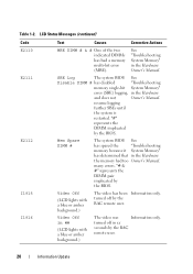
...'s Manual. "#" represents the DIMM implicated by the BIOS. Mem Spare DIMM # The system BIOS See has spared the "Troubleshooting memory because it System Memory" has determined that in ## (LCD lights with a blue or amber background.) The video has been Information only. Video Off ... Table 1-2. "# & #" represents the DIMM pair implicated by the BIOS. turned off in the Hardware Owner's Manual. See "Troubleshooting System Memory" in xx seconds by the RAC remote user. turned off by the RAC remote user. 20 Information Update many errors. SBE Log The ...
...'s Manual. "#" represents the DIMM implicated by the BIOS. Mem Spare DIMM # The system BIOS See has spared the "Troubleshooting memory because it System Memory" has determined that in ## (LCD lights with a blue or amber background.) The video has been Information only. Video Off ... Table 1-2. "# & #" represents the DIMM pair implicated by the BIOS. turned off in the Hardware Owner's Manual. See "Troubleshooting System Memory" in xx seconds by the RAC remote user. turned off by the RAC remote user. 20 Information Update many errors. SBE Log The ...
Information Update
Page 21
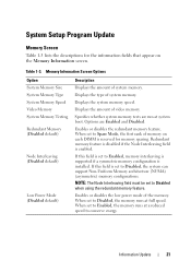
.... NOTE: The Node Interleaving field must be set to Disabled, the memory runs at full speed. When set to Disabled when using the redundant memory feature. Memory Information Screen Options Option System Memory Size System Memory Type System Memory Speed Video Memory System Memory Testing Redundant Memory (Disabled default) Node Interleaving (Disabled default) Low Power Mode (Disabled default) Description...
.... NOTE: The Node Interleaving field must be set to Disabled, the memory runs at full speed. When set to Disabled when using the redundant memory feature. Memory Information Screen Options Option System Memory Size System Memory Type System Memory Speed Video Memory System Memory Testing Redundant Memory (Disabled default) Node Interleaving (Disabled default) Low Power Mode (Disabled default) Description...

Information Update
Page 26
System Diagnostics Custom Test Options In the Customize window of the system diagnostics, the Log output file pathname option enables you to a hard drive. 26 Information Update You cannot save the file to specify the diskette drive or USB memory key where the test log file is saved. Hardware Owner's Manual Updates Installing the Processor When installing the processor, the processor shield must be closed before securing the processor with the socket release lever.
System Diagnostics Custom Test Options In the Customize window of the system diagnostics, the Log output file pathname option enables you to a hard drive. 26 Information Update You cannot save the file to specify the diskette drive or USB memory key where the test log file is saved. Hardware Owner's Manual Updates Installing the Processor When installing the processor, the processor shield must be closed before securing the processor with the socket release lever.
Information Update
Page 31
POST Non-Optimal Memory Configuration Press F1 to continue or F2 for Setup (按 F1 F2 DIMM DIMM PowerEdge 1950 III 全新性能 Intel® Xeon® 5400 系列和 5300 8 GB BMC 使用。 全新 I/O • 可选 Intel NIC 10 Mbps、100 Mbps 和 1000 Mbps iSCSI • 支持 10 Gb USB 2.0 USB USB SAS 6i/R 和 PERC 6/i 信息更新 31
POST Non-Optimal Memory Configuration Press F1 to continue or F2 for Setup (按 F1 F2 DIMM DIMM PowerEdge 1950 III 全新性能 Intel® Xeon® 5400 系列和 5300 8 GB BMC 使用。 全新 I/O • 可选 Intel NIC 10 Mbps、100 Mbps 和 1000 Mbps iSCSI • 支持 10 Gb USB 2.0 USB USB SAS 6i/R 和 PERC 6/i 信息更新 31

Information Update
Page 36
Memory DIMM configuration does not support Node Interleaving. !!*** Error: Remote Access Controller 失败。 initialization failure *** RAC virtual USB devices may not be available... found in the Internal_Storage slot! (在 Internal_Storage PCIe 卡!) PCIe PCIe SAS 36 信息更新 表 1-1 列出 PowerEdge 1950 III 表 1-1 信息 原因 纠正措施 Alert!Node Interleaving disabled!
Memory DIMM configuration does not support Node Interleaving. !!*** Error: Remote Access Controller 失败。 initialization failure *** RAC virtual USB devices may not be available... found in the Internal_Storage slot! (在 Internal_Storage PCIe 卡!) PCIe PCIe SAS 36 信息更新 表 1-1 列出 PowerEdge 1950 III 表 1-1 信息 原因 纠正措施 Alert!Node Interleaving disabled!
Information Update
Page 39
... could prevent security. (TPM I M 按 I M 修改 TPM Warning: Following faulty DIMMs are disabled DIMM DIMM n1 和 n2 DIMM DIMM n1 n2 Total memory size is reduced Warning: A fatal error has caused system reset!Please check the system event log 请查看 SEL SEL 信息更新...
... could prevent security. (TPM I M 按 I M 修改 TPM Warning: Following faulty DIMMs are disabled DIMM DIMM n1 和 n2 DIMM DIMM n1 n2 Total memory size is reduced Warning: A fatal error has caused system reset!Please check the system event log 请查看 SEL SEL 信息更新...
Information Update
Page 40
表 1-1 信息 原因 纠正措施 Warning! No micro code update loaded for processor n n 请更新 BIOS Warning: The installed memory configuration is not optimal. For more information on valid memory configurations, please see the system documentation on the technical support web site Write fault USB 设备、USB Write fault on selected drive USB 设备或 USB 40 信息更新
表 1-1 信息 原因 纠正措施 Warning! No micro code update loaded for processor n n 请更新 BIOS Warning: The installed memory configuration is not optimal. For more information on valid memory configurations, please see the system documentation on the technical support web site Write fault USB 设备、USB Write fault on selected drive USB 设备或 USB 40 信息更新

Information Update
Page 45
内存屏幕 表 1-3 列出了 Memory Information 表 1-3. Memory Information 选项 System Memory Size System Memory Type System Memory Speed Video Memory System Memory Testing Redundant Memory Disabled Node Interleaving Disabled Low Power Mode Disabled Enabled Disabled Spare Mode DIMM Node Interleaving Enabled Disabled NUMA Node Interleaving Disabled Disabled Enabled 信息更新 45
内存屏幕 表 1-3 列出了 Memory Information 表 1-3. Memory Information 选项 System Memory Size System Memory Type System Memory Speed Video Memory System Memory Testing Redundant Memory Disabled Node Interleaving Disabled Low Power Mode Disabled Enabled Disabled Spare Mode DIMM Node Interleaving Enabled Disabled NUMA Node Interleaving Disabled Disabled Enabled 信息更新 45
Information Update
Page 115
POST Non-Optimal Memory Configuration Press F1 to continue or F2 for Setup F1 F2 DIMM DIMM DIMM PowerEdge 1950 III Intel® Xeon® 5400 5300 2 個。 • 8 GB BMC 115
POST Non-Optimal Memory Configuration Press F1 to continue or F2 for Setup F1 F2 DIMM DIMM DIMM PowerEdge 1950 III Intel® Xeon® 5400 5300 2 個。 • 8 GB BMC 115
Information Update
Page 121
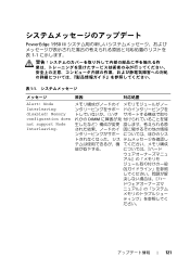
Memory configuration does not support Node Interleaving. れかの DIMM ださい。 121 PowerEdge 1950 III 1-1 表 1-1 原因 対応処置 Alert! Node Interleaving disabled!
Memory configuration does not support Node Interleaving. れかの DIMM ださい。 121 PowerEdge 1950 III 1-1 表 1-1 原因 対応処置 Alert! Node Interleaving disabled!


