Rack Installation Guide
Page 4
... Kit Contents One Rack Unit Marking the Vertical Rails Installing the RapidRails Slide Assemblies . . . Figure 1-3. Figure 1-12. Figure 1-15. Opening the Wire Covers Installing the Power Cord Strain Relief . . . Figure 1-5. Figure 1-16. Figure 1-17. Routing Cables Two-Post Rack Kit Components Two-Post, Open-Frame Relay Rack Universal-Hole Spacing Two...
... Kit Contents One Rack Unit Marking the Vertical Rails Installing the RapidRails Slide Assemblies . . . Figure 1-3. Figure 1-12. Figure 1-15. Opening the Wire Covers Installing the Power Cord Strain Relief . . . Figure 1-5. Figure 1-16. Figure 1-17. Routing Cables Two-Post Rack Kit Components Two-Post, Open-Frame Relay Rack Universal-Hole Spacing Two...

Rack Installation Guide
Page 6
...result in troubleshooting and the identification of system health, some rack kits include a status-indicator cable assembly that provides power to the rack. Installation Instructions This installation guide provides instructions for trained service technicians installing one or more information on...component is provided to be installed in an open-frame relay rack. the slide rails can be installed in a rack. www.dell.com | support.dell.com CAUTION: Safety Instructions (continued) • Use caution when pressing the component rail release latches and sliding a component into ...
...result in troubleshooting and the identification of system health, some rack kits include a status-indicator cable assembly that provides power to the rack. Installation Instructions This installation guide provides instructions for trained service technicians installing one or more information on...component is provided to be installed in an open-frame relay rack. the slide rails can be installed in a rack. www.dell.com | support.dell.com CAUTION: Safety Instructions (continued) • Use caution when pressing the component rail release latches and sliding a component into ...

Rack Installation Guide
Page 18
www.dell.com | support.dell.com 7 Route the status-indicator end of the cable assembly through the slot on the strain-relief tab (see Figure 1-10). 10 Bend the power cords back beside the power receptacle housing, forming a tight loop, and install the strain-relief tie-wrap loosely around the looped power cords (see Figure 1-10...
www.dell.com | support.dell.com 7 Route the status-indicator end of the cable assembly through the slot on the strain-relief tab (see Figure 1-10). 10 Bend the power cords back beside the power receptacle housing, forming a tight loop, and install the strain-relief tie-wrap loosely around the looped power cords (see Figure 1-10...

Rack Installation Guide
Page 19
... vertical rail. c Route the cables along the cable-management arm, make any adjustments to the cable slack at this time (see Figure 1-11). 2 Route the power and I/O cables through the cable-management arm, using four loosely secured releasable tie wraps (two in the middle and on the side of the slide...
... vertical rail. c Route the cables along the cable-management arm, make any adjustments to the cable slack at this time (see Figure 1-11). 2 Route the power and I/O cables through the cable-management arm, using four loosely secured releasable tie wraps (two in the middle and on the side of the slide...
Microprocessor Upgrade Installation Guide
Page 3
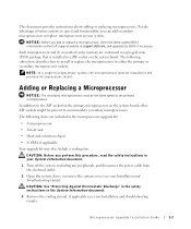
...Electrostatic Discharge" in the safety instructions in your System Information document. 1 Turn off the system, including any peripherals, and disconnect the power cable from the electrical outlet. 2 Open the system doors, or remove the system cover (see your system. Each microprocessor and its ... In a single microprocessor system, the microprocessor must be present to the ZIF socket for the primary microprocessor on the Dell Support website at support.dell.com, and upgrade the BIOS if necessary. NOTICE: Before you can add secondary microprocessors or replace microprocessors in the ...
...Electrostatic Discharge" in the safety instructions in your System Information document. 1 Turn off the system, including any peripherals, and disconnect the power cable from the electrical outlet. 2 Open the system doors, or remove the system cover (see your system. Each microprocessor and its ... In a single microprocessor system, the microprocessor must be present to the ZIF socket for the primary microprocessor on the Dell Support website at support.dell.com, and upgrade the BIOS if necessary. NOTICE: Before you can add secondary microprocessors or replace microprocessors in the ...
Cabling Instructions for –48 VDC
Page 3
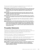
...ground conductor or operate the equipment in accordance with 90ºC wire. All electrical wiring must comply with a -48 VDC power supply. Do not attempt to connect power to the system until grounding cables are uncertain whether suitable grounding is available. CAUTION: Before connecting safety ground or...secured to prevent an energy hazard. The system must always be safety grounded at the cabinet frame. Switch the circuit breaker to DC power and safety grounds. Read and follow all connections to the off , locate the circuit breaker on the DC source circuit. To ...
...ground conductor or operate the equipment in accordance with 90ºC wire. All electrical wiring must comply with a -48 VDC power supply. Do not attempt to connect power to the system until grounding cables are uncertain whether suitable grounding is available. CAUTION: Before connecting safety ground or...secured to prevent an energy hazard. The system must always be safety grounded at the cabinet frame. Switch the circuit breaker to DC power and safety grounds. Read and follow all connections to the off , locate the circuit breaker on the DC source circuit. To ...

Cabling Instructions for –48 VDC
Page 4
NOTE: If your system is equipped with redundant -48 VDC power supplies, you removed in step 1 (see Figure 1-1). www.dell.com | support.dell.com Input Requirements • Supply voltage: -(38-60) VDC • Current consumption: 7.5 A Connecting the -48 VDC Power Cable and Safety Ground 1 Remove the #6-32 nut equipped with a lock washer from the grounding...
NOTE: If your system is equipped with redundant -48 VDC power supplies, you removed in step 1 (see Figure 1-1). www.dell.com | support.dell.com Input Requirements • Supply voltage: -(38-60) VDC • Current consumption: 7.5 A Connecting the -48 VDC Power Cable and Safety Ground 1 Remove the #6-32 nut equipped with a lock washer from the grounding...

Cabling Instructions for –48 VDC
Page 5
3 Plug the DC power cable into the system. See your Rack Installation Guide for the -48 VDC 1-3 Figure 1-2. Connector Housing Pin Assignments Pin Description 1 -48 VDC 2 -48 VDC return Wire Color and Size Black 14 AWG Red 14 AWG Cabling Instructions for information on routing cables. DC Input Power Cable Connector's Pin Orientation 2 1 Table 1-1. Figure 1-2 and Table 1-1 indicate the DC input power cable connector's pin orientation and descriptions.
3 Plug the DC power cable into the system. See your Rack Installation Guide for the -48 VDC 1-3 Figure 1-2. Connector Housing Pin Assignments Pin Description 1 -48 VDC 2 -48 VDC return Wire Color and Size Black 14 AWG Red 14 AWG Cabling Instructions for information on routing cables. DC Input Power Cable Connector's Pin Orientation 2 1 Table 1-1. Figure 1-2 and Table 1-1 indicate the DC input power cable connector's pin orientation and descriptions.


