
Hardware Guide
Page 2
... 4.4BSD-Lite Releases is subject to change without notice. Dell PowerConnect J-Series J-EX4500 Ethernet Switch Hardware Guide © Copyright Juniper Networks, Inc. , 2011. END USER LICENSE AGREEMENT READ THIS END USER LICENSE AGREEMENT ("AGREEMENT") BEFORE DOWNLOADING, INSTALLING, OR USING THE SOFTWARE. The Regents of the University of their respective owners. Reproduction of GateD has been supported in the revision history. in this document. IF YOU DO NOT OR...
... 4.4BSD-Lite Releases is subject to change without notice. Dell PowerConnect J-Series J-EX4500 Ethernet Switch Hardware Guide © Copyright Juniper Networks, Inc. , 2011. END USER LICENSE AGREEMENT READ THIS END USER LICENSE AGREEMENT ("AGREEMENT") BEFORE DOWNLOADING, INSTALLING, OR USING THE SOFTWARE. The Regents of the University of their respective owners. Reproduction of GateD has been supported in the revision history. in this document. IF YOU DO NOT OR...

Hardware Guide
Page 3
... to a maximum number of seats, registered endpoints, concurrent users, sessions, calls, connections, subscribers, clusters, nodes, realms, devices, links, ports or transactions, or require the purchase of Juniper; d. e. Specifically, service provider customers are physically contained on multiple computers or virtual machines (e.g., Solaris zones) requires multiple licenses, regardless of the Steel-Belted Radius software may restrict the use particular features, functionalities, services, applications, operations, or...
... to a maximum number of seats, registered endpoints, concurrent users, sessions, calls, connections, subscribers, clusters, nodes, realms, devices, links, ports or transactions, or require the purchase of Juniper; d. e. Specifically, service provider customers are physically contained on multiple computers or virtual machines (e.g., Solaris zones) requires multiple licenses, regardless of the Steel-Belted Radius software may restrict the use particular features, functionalities, services, applications, operations, or...
Hardware Guide
Page 9
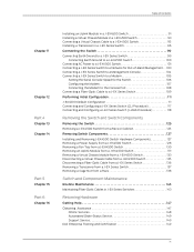
...Setting the Serial Console Speed for the Switch 106 Configuring the Modem 107 Connecting the Modem to the Console Port 108 Connecting a Fiber-Optic Cable to a J-EX Series Switch 109 Performing Initial Configuration 111 J-EX4500 Default Configuration 111 Connecting and Configuring a J-EX Series Switch (CLI Procedure 117 Connecting and Configuring a J-EX Series Switch (J-Web Procedure 118 Removing the Switch and Switch Components Removing the Switch 125 Removing a J-EX4500 Switch from a Rack or Cabinet 125 Removing Switch Components 127 Installing and Removing J-EX4500 Switch Hardware...
...Setting the Serial Console Speed for the Switch 106 Configuring the Modem 107 Connecting the Modem to the Console Port 108 Connecting a Fiber-Optic Cable to a J-EX Series Switch 109 Performing Initial Configuration 111 J-EX4500 Default Configuration 111 Connecting and Configuring a J-EX Series Switch (CLI Procedure 117 Connecting and Configuring a J-EX Series Switch (J-Web Procedure 118 Removing the Switch and Switch Components Removing the Switch 125 Removing a J-EX4500 Switch from a Rack or Cabinet 125 Removing Switch Components 127 Installing and Removing J-EX4500 Switch Hardware...

Hardware Guide
Page 21
... J-EX4500 switches and up to core devices in a switch. The Virtual Chassis module is an offline field-replaceable unit (FRU). Chapter 1: Dell PowerConnect J-Series J-EX4500 Switch Overview NOTE: The network ports are available for connecting to eight J-EX4200 switches. To provide carrier-class reliability, J-EX4500 switches include: • Dual redundant, load-sharing power supplies that are field-replaceable, hot-removable, and hot-insertable. • A field-replaceable fan tray with J-EX4200 switches or another J-EX4500 switch...
... J-EX4500 switches and up to core devices in a switch. The Virtual Chassis module is an offline field-replaceable unit (FRU). Chapter 1: Dell PowerConnect J-Series J-EX4500 Switch Overview NOTE: The network ports are available for connecting to eight J-EX4200 switches. To provide carrier-class reliability, J-EX4500 switches include: • Dual redundant, load-sharing power supplies that are field-replaceable, hot-removable, and hot-insertable. • A field-replaceable fan tray with J-EX4200 switches or another J-EX4500 switch...
Hardware Guide
Page 25
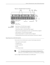
... 31 Network ports 33 35 37 39 MGMT Management port Enter button Console port ESD point USB port 1 3 1, 3, 5, 7.... 39 Lower port numbers Related • Rear Panel of a J-EX4500 Switch on page 9 Documentation • LCD Panel in J-EX4500 Switches on page 13 • Chassis Status LEDs in J-EX4500 Switches on page 17 • Network Port and Uplink Module Port LEDs in J-EX4500 Switches on page 18 • Uplink Modules in J-EX4500 Switches on page 27 • Optical Interface Support in J-EX4500 Switches on page 40 • Installing and Removing J-EX4500 Switch Hardware...
... 31 Network ports 33 35 37 39 MGMT Management port Enter button Console port ESD point USB port 1 3 1, 3, 5, 7.... 39 Lower port numbers Related • Rear Panel of a J-EX4500 Switch on page 9 Documentation • LCD Panel in J-EX4500 Switches on page 13 • Chassis Status LEDs in J-EX4500 Switches on page 17 • Network Port and Uplink Module Port LEDs in J-EX4500 Switches on page 18 • Uplink Modules in J-EX4500 Switches on page 27 • Optical Interface Support in J-EX4500 Switches on page 40 • Installing and Removing J-EX4500 Switch Hardware...

Hardware Guide
Page 29
... Series switches in the Dell PowerConnect J-Series Ethernet Switch Complete Software Guide for configuring the LCD panel on page 13. If the LCD panel is configured to perform basic operations such as initial setup and reboot. CHAPTER 2 Component Descriptions • LCD Panel in J-EX4500 Switches on page 13 • Chassis Status LEDs in J-EX4500 Switches on page 17 • Field-Replaceable Units in J-EX4500 Switches on page 18 • Network Port and Uplink Module Port LEDs in J-EX4500 Switches on...
... Series switches in the Dell PowerConnect J-Series Ethernet Switch Complete Software Guide for configuring the LCD panel on page 13. If the LCD panel is configured to perform basic operations such as initial setup and reboot. CHAPTER 2 Component Descriptions • LCD Panel in J-EX4500 Switches on page 13 • Chassis Status LEDs in J-EX4500 Switches on page 17 • Field-Replaceable Units in J-EX4500 Switches on page 18 • Network Port and Uplink Module Port LEDs in J-EX4500 Switches on...

Hardware Guide
Page 30
... by pressing the Enter button. If the LCD panel remains idle for Junos OS at http://www.support.dell.com/manuals. The boot mode displays the key milestones in idle, status, or maintenance mode, you can turn on page 14 The LCD panel operates in the Dell PowerConnect J-Series Ethernet Switch Complete Software Guide for 60 seconds, the backlight turns off. For a standalone J-EX4500 switch, the slot number is always 00 and...
... by pressing the Enter button. If the LCD panel remains idle for Junos OS at http://www.support.dell.com/manuals. The boot mode displays the key milestones in idle, status, or maintenance mode, you can turn on page 14 The LCD panel operates in the Dell PowerConnect J-Series Ethernet Switch Complete Software Guide for 60 seconds, the backlight turns off. For a standalone J-EX4500 switch, the slot number is always 00 and...
Hardware Guide
Page 33
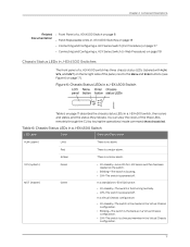
... Status LEDs in a J-EX4500 Switch Table 6 on page 17). SYS (system) MST (master) Green Green • On steadily-Junos OS for J-EX Series switches has been loaded on the switch. • Blinking-The switch is booting. • Off-The switch is no alarm. Chapter 2: Component Descriptions Related • Front Panel of a J-EX4500 Switch on page 8 Documentation • Field-Replaceable Units in J-EX4500 Switches on page 18 • Connecting and Configuring a J-EX Series Switch (CLI Procedure...
... Status LEDs in a J-EX4500 Switch Table 6 on page 17). SYS (system) MST (master) Green Green • On steadily-Junos OS for J-EX Series switches has been loaded on the switch. • Blinking-The switch is booting. • Off-The switch is no alarm. Chapter 2: Component Descriptions Related • Front Panel of a J-EX4500 Switch on page 8 Documentation • Field-Replaceable Units in J-EX4500 Switches on page 18 • Connecting and Configuring a J-EX Series Switch (CLI Procedure...
Hardware Guide
Page 36
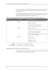
... disabled. The status indicators are administrative status, duplex mode, and speed. therefore, the LED is set to half-duplex mode. Dell PowerConnect J-Series J-EX4500 Ethernet Switch Hardware Guide The Status LED in J-EX4500 Switches LED LCD Indicator State and Description Status LED: ADM LED: DPX Indicates the administrative status (enabled or disabled). Table 8: Status LED on Network Ports and Uplink Module Ports in Figure 7 on page 19 and Figure 8 on page 19 indicate the status of one of a J-EX4500 switch has two LEDs that indicate link/activity and port status...
... disabled. The status indicators are administrative status, duplex mode, and speed. therefore, the LED is set to half-duplex mode. Dell PowerConnect J-Series J-EX4500 Ethernet Switch Hardware Guide The Status LED in J-EX4500 Switches LED LCD Indicator State and Description Status LED: ADM LED: DPX Indicates the administrative status (enabled or disabled). Table 8: Status LED on Network Ports and Uplink Module Ports in Figure 7 on page 19 and Figure 8 on page 19 indicate the status of one of a J-EX4500 switch has two LEDs that indicate link/activity and port status...

Hardware Guide
Page 93
...rack or cabinet 8 Accessory kit box 1 Quick Start installation instructions 1 Dell PowerConnect Safety, Environmental, and Regulatory Information 1 End User License Agreement 1 DellPowerConnect Warranty and Support Information 1 Registration and Software Updates for Your Dell PowerConnect J-Series Product 1 Open Source Code Notice 1 Ethernet cable, RJ-45/RJ-45, 4-pair stranded UTP, category #5 1 RJ-45-to-DB-9 serial port adapter 1 Related • Installing and Connecting a J-EX4500 Switch on page 75 Documentation • Connecting and Configuring a J-EX Series Switch (CLI...
...rack or cabinet 8 Accessory kit box 1 Quick Start installation instructions 1 Dell PowerConnect Safety, Environmental, and Regulatory Information 1 End User License Agreement 1 DellPowerConnect Warranty and Support Information 1 Registration and Software Updates for Your Dell PowerConnect J-Series Product 1 Open Source Code Notice 1 Ethernet cable, RJ-45/RJ-45, 4-pair stranded UTP, category #5 1 RJ-45-to-DB-9 serial port adapter 1 Related • Installing and Connecting a J-EX4500 Switch on page 75 Documentation • Connecting and Configuring a J-EX Series Switch (CLI...
Hardware Guide
Page 109
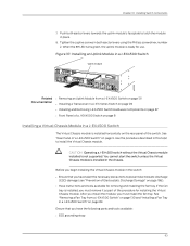
... a J-EX4500 Switch" on page 89. See "Removing a Fan Tray from a J-EX4500 Switch on page 131 Documentation • Installing a Transceiver in a J-EX Series Switch on page 96 • Installing and Removing J-EX4500 Switch Hardware Components on page 87 • Front Panel of a J-EX4500 Switch on page 130 and "Installing a Fan Tray in place. 8. When the ST LED turns green, the uplink module is not supported. Figure 37: Installing an Uplink Module in a J-EX4500 Switch Uplink module 0 1 2 3 ST 0 1 2 3 ST g020834 Related • Removing an Uplink Module from a J-EX4500 Switch...
... a J-EX4500 Switch" on page 89. See "Removing a Fan Tray from a J-EX4500 Switch on page 131 Documentation • Installing a Transceiver in a J-EX Series Switch on page 96 • Installing and Removing J-EX4500 Switch Hardware Components on page 87 • Front Panel of a J-EX4500 Switch on page 130 and "Installing a Fan Tray in place. 8. When the ST LED turns green, the uplink module is not supported. Figure 37: Installing an Uplink Module in a J-EX4500 Switch Uplink module 0 1 2 3 ST 0 1 2 3 ST g020834 Related • Removing an Uplink Module from a J-EX4500 Switch...

Hardware Guide
Page 119
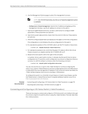
...: Ethernet Cable Connector To connect a J-EX Series switch to the ON (|) position. 10. For the location of the MGMT port, see Figure 45 on the J-EX Series switch. Figure 43: Connecting the Power Supply Cord to the management device. Use the management port to connect the J-EX Series switch to a J-EX4500 Switch Retainer clip Tighten adjustment nut. Repeat Steps 2 through 10 for Out-of a J-EX4500 Switch" on page 21 Documentation • AC Power Supply LEDs in...
...: Ethernet Cable Connector To connect a J-EX Series switch to the ON (|) position. 10. For the location of the MGMT port, see Figure 45 on the J-EX Series switch. Figure 43: Connecting the Power Supply Cord to the management device. Use the management port to connect the J-EX Series switch to a J-EX4500 Switch Retainer clip Tighten adjustment nut. Repeat Steps 2 through 10 for Out-of a J-EX4500 Switch" on page 21 Documentation • AC Power Supply LEDs in...

Hardware Guide
Page 121
... Series Switch Directly to a Management Console Related • Connecting a J-EX Series Switch to a Network for Out-of the switch. Connect the other end of the CON/CONSOLE port, see "Connecting and Configuring a J-EX Series Switch (CLI Procedure)" on page 117 or "Connecting and Configuring a J-EX Series Switch (J-Web Procedure)" on page 118. See "Connecting and Configuring a J-EX Series Switch (CLI Procedure)" on page 117 or "Connecting and Configuring a J-EX Series Switch (J-Web Procedure)" on the switch. For the location of the Ethernet cable into the console port...
... Series Switch Directly to a Management Console Related • Connecting a J-EX Series Switch to a Network for Out-of the switch. Connect the other end of the CON/CONSOLE port, see "Connecting and Configuring a J-EX Series Switch (CLI Procedure)" on page 117 or "Connecting and Configuring a J-EX Series Switch (J-Web Procedure)" on page 118. See "Connecting and Configuring a J-EX Series Switch (CLI Procedure)" on page 117 or "Connecting and Configuring a J-EX Series Switch (J-Web Procedure)" on the switch. For the location of the Ethernet cable into the console port...
Hardware Guide
Page 134
... configuration set the PIC mode to the right of -band management. Dell PowerConnect J-Series J-EX4500 Ethernet Switch Hardware Guide 6. A lit amber (minor) alarm LED is using the J-Web interface. If the connection cannot be made, the J-Web interface displays instructions for the switch. 10. Select the time zone from the list. It indicates that the VC MODE LED is on page 75 Connecting and Configuring a J-EX Series Switch (J-Web Procedure) There are optional. 8. For standalone operation only, verify that the green ST (status) LED...
... configuration set the PIC mode to the right of -band management. Dell PowerConnect J-Series J-EX4500 Ethernet Switch Hardware Guide 6. A lit amber (minor) alarm LED is using the J-Web interface. If the connection cannot be made, the J-Web interface displays instructions for the switch. 10. Select the time zone from the list. It indicates that the VC MODE LED is on page 75 Connecting and Configuring a J-EX Series Switch (J-Web Procedure) There are optional. 8. For standalone operation only, verify that the green ST (status) LED...
Hardware Guide
Page 135
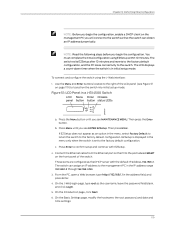
... to the factory default configuration, and the PC loses connectivity to transition the switch into initial setup mode: Figure 51: LCD Panel in the IP address range 192.168.1.2 through 192.168.1.253. 3. Use the Menu and Enter buttons located to the right of the switch. b. These ports are configured as the DHCP server with EZSetup. 2. Then press the Enter button. Connect the Ethernet cable from the Ethernet port on the...
... to the factory default configuration, and the PC loses connectivity to transition the switch into initial setup mode: Figure 51: LCD Panel in the IP address range 192.168.1.2 through 192.168.1.253. 3. Use the Menu and Enter buttons located to the right of the switch. b. These ports are configured as the DHCP server with EZSetup. 2. Then press the Enter button. Connect the Ethernet cable from the Ethernet port on the...

Hardware Guide
Page 136
... LED is off. 14. For SNMP, you can return to continue configuring the switch. To renew the connection, release and renew the IP address by executing the appropriate commands on steadily and that you can now use the J-Web interface to enable Telnet, SSH, and SNMP services. The Summary screen displays the configured settings. 11. If you may select options to continue configuring the switch, the Web session is optional. Dell PowerConnect J-Series J-EX4500 Ethernet Switch Hardware Guide...
... LED is off. 14. For SNMP, you can return to continue configuring the switch. To renew the connection, release and renew the IP address by executing the appropriate commands on steadily and that you can now use the J-Web interface to enable Telnet, SSH, and SNMP services. The Summary screen displays the configured settings. 11. If you may select options to continue configuring the switch, the Web session is optional. Dell PowerConnect J-Series J-EX4500 Ethernet Switch Hardware Guide...

Hardware Guide
Page 149
... Module from a J-EX4500 Switch The Virtual Chassis module is installed horizontally on the rear panel of Electrostatic Discharge Damage" on page 186). • Have instructions and tools for removing the fan tray. Before you begin removing the Virtual Chassis module from the switch before removing the Virtual Chassis module. See "Removing a Fan Tray from the switch (see "Prevention of the switch. Halt the switch using the request system halt CLI command: user@switch...
... Module from a J-EX4500 Switch The Virtual Chassis module is installed horizontally on the rear panel of Electrostatic Discharge Damage" on page 186). • Have instructions and tools for removing the fan tray. Before you begin removing the Virtual Chassis module from the switch before removing the Virtual Chassis module. See "Removing a Fan Tray from the switch (see "Prevention of the switch. Halt the switch using the request system halt CLI command: user@switch...
Hardware Guide
Page 164
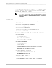
... can access Dell Support through the following services are not always available in as user: anonymous, and use your e-mail address as your Express Service Code to route the call directly to the proper support personnel. Dell PowerConnect J-Series J-EX4500 Ethernet Switch Hardware Guide Online Services When prompted by Dell's automated telephone system, enter your password. 148 For instructions on using the Dell Support, see "Support Service" on availability. NOTE: Some of the following websites and e-mail addresses: • Dell Support...
... can access Dell Support through the following services are not always available in as user: anonymous, and use your e-mail address as your Express Service Code to route the call directly to the proper support personnel. Dell PowerConnect J-Series J-EX4500 Ethernet Switch Hardware Guide Online Services When prompted by Dell's automated telephone system, enter your password. 148 For instructions on using the Dell Support, see "Support Service" on availability. NOTE: Some of the following websites and e-mail addresses: • Dell Support...

Hardware Guide
Page 220
... 16 204 Dell PowerConnect J-Series J-EX4500 Ethernet Switch Hardware Guide components for each model 6 installation 87 list by model 6 overview 1 packing for shipping 156 provided with 55 requirements 196 standards 195 EMI (electromagnetic interference) standards 195 suppressing 55 ENTER EZSETUP? on power supply and fan tray 23, 26 EZSetup configuring the switch with J-Web 119 configuring the switch with the CLI 117 launching from the LCD panel 16 F factory default configuration 111 restoring from the...
... 16 204 Dell PowerConnect J-Series J-EX4500 Ethernet Switch Hardware Guide components for each model 6 installation 87 list by model 6 overview 1 packing for shipping 156 provided with 55 requirements 196 standards 195 EMI (electromagnetic interference) standards 195 suppressing 55 ENTER EZSETUP? on power supply and fan tray 23, 26 EZSetup configuring the switch with J-Web 119 configuring the switch with the CLI 117 launching from the LCD panel 16 F factory default configuration 111 restoring from the...

Hardware Guide
Page 222
... models, switch identifying 7 overview 6 modem connection configuring the modem 107 connecting 105 setting the serial console speed 106 modes of operation, LCD panel 14 MST (master) LED 17 N network cable connecting for out-of-band management 103 connecting to a management console 104 specifications 63 network ports LED locations 19 Link/Activity LED 19 locations 9 pinouts 35 status indicators on LCD panel 15 Status LEDs 20 New Zealand-Australia Declaration of Conformity 198 O online services, Dell 148 optical interfaces 40 order status, checking...
... models, switch identifying 7 overview 6 modem connection configuring the modem 107 connecting 105 setting the serial console speed 106 modes of operation, LCD panel 14 MST (master) LED 17 N network cable connecting for out-of-band management 103 connecting to a management console 104 specifications 63 network ports LED locations 19 Link/Activity LED 19 locations 9 pinouts 35 status indicators on LCD panel 15 Status LEDs 20 New Zealand-Australia Declaration of Conformity 198 O online services, Dell 148 optical interfaces 40 order status, checking...

