
Page 4
... High Port Count 56 Single IP Management 56 Automatic Firmware Upgrade for New Stack Members 56 Stacking Compatibility with the PowerConnect M6348 56 Master Failover with Transparent Transition . . . . 57 Nonstop Forwarding on the Stack 57 Hot Add/Delete and Firmware Synchronization 57 Security Features 57 Configurable Access and Authentication Profiles 57 Password-Protected Management...
... High Port Count 56 Single IP Management 56 Automatic Firmware Upgrade for New Stack Members 56 Stacking Compatibility with the PowerConnect M6348 56 Master Failover with Transparent Transition . . . . 57 Nonstop Forwarding on the Stack 57 Hot Add/Delete and Firmware Synchronization 57 Security Features 57 Configurable Access and Authentication Profiles 57 Password-Protected Management...

Page 8
Out-of-Band Management Port 85 USB Port 85 Reset Button 86 Port and System LEDs 86 Stack Master LED and Stack Number Display . . . 86 PowerConnect 7000 Series Back Panel 87 Expansion Slots for Plug-in Modules 88 Power Supplies 89 Ventilation System 90 ...Locator LED 90 LED Definitions 91 Port LEDs 91 Module LEDs 93 System LEDs 95 4 Using Dell OpenManage Switch Administrator 97 About Dell OpenManage Switch Administrator. ...
Out-of-Band Management Port 85 USB Port 85 Reset Button 86 Port and System LEDs 86 Stack Master LED and Stack Number Display . . . 86 PowerConnect 7000 Series Back Panel 87 Expansion Slots for Plug-in Modules 88 Power Supplies 89 Ventilation System 90 ...Locator LED 90 LED Definitions 91 Port LEDs 91 Module LEDs 93 System LEDs 95 4 Using Dell OpenManage Switch Administrator 97 About Dell OpenManage Switch Administrator. ...
Page 10
... Network Information Configuration Example 132 8 Managing a Switch Stack 135 Stacking Overview 135 PowerConnect 7000 Series and M6348 Stacking Compatibility 137 How is the Management Unit Selected? . . . . . 137 Adding a Switch to the Stack 138 Removing a Switch from the Stack 139 How is the Firmware Updated on the Stack?. . . 140 What is Stacking Standby 140 What is Nonstop Forwarding 140...
... Network Information Configuration Example 132 8 Managing a Switch Stack 135 Stacking Overview 135 PowerConnect 7000 Series and M6348 Stacking Compatibility 137 How is the Management Unit Selected? . . . . . 137 Adding a Switch to the Stack 138 Removing a Switch from the Stack 139 How is the Firmware Updated on the Stack?. . . 140 What is Stacking Standby 140 What is Nonstop Forwarding 140...
Page 11
... Considerations 144 Why is Stacking Needed 144 Default Stacking Values 145 Managing and Monitoring the Stack (Web 146 Unit Configuration 146 Stack Summary 148 Stack Firmware Synchronization 149 Supported Switches 150 Stack Port Summary 151 Stack Port Counters 152 Stack Port Diagnostics 152 NSF Summary 153 Checkpoint Statistics 154 Managing the Stack (CLI 155 Configuring Stack Member and NSF Settings...
... Considerations 144 Why is Stacking Needed 144 Default Stacking Values 145 Managing and Monitoring the Stack (Web 146 Unit Configuration 146 Stack Summary 148 Stack Firmware Synchronization 149 Supported Switches 150 Stack Port Summary 151 Stack Port Counters 152 Stack Port Diagnostics 152 NSF Summary 153 Checkpoint Statistics 154 Managing the Stack (CLI 155 Configuring Stack Member and NSF Settings...

Page 34
... 837 How Is the Address Table Populated 837 What Information Is in the MAC Address Table 838 How Is the MAC Address Table Maintained Across a Stack 838 Default MAC Address Table Values 838 Managing the MAC Address Table (Web 839 Static Address Table 839 Dynamic Address Table 841 Managing the MAC...
... 837 How Is the Address Table Populated 837 What Information Is in the MAC Address Table 838 How Is the MAC Address Table Maintained Across a Stack 838 Default MAC Address Table Values 838 Managing the MAC Address Table (Web 839 Static Address Table 839 Dynamic Address Table 841 Managing the MAC...
Page 49
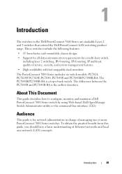
... requirements for network administrators in the Dell PowerConnect 7000 Series are stackable Layer 2 and 3 switches that extend the Dell PowerConnect LAN switching product range. The PowerConnect 7000 Series includes six switch models:... PC7024, PC7024P, PC7024F, PC7048, PC7048P, and PC7048R/PC7048R-RA. To obtain the greatest benefit from this guide, you should have a basic understanding of service, security, and system management features. • High availability with hot swappable stack...
... requirements for network administrators in the Dell PowerConnect 7000 Series are stackable Layer 2 and 3 switches that extend the Dell PowerConnect LAN switching product range. The PowerConnect 7000 Series includes six switch models:... PC7024, PC7024P, PC7024F, PC7048, PC7048P, and PC7048R/PC7048R-RA. To obtain the greatest benefit from this guide, you should have a basic understanding of service, security, and system management features. • High availability with hot swappable stack...

Page 51
...-configurable software features. The topics covered in this product. NOTE: Before proceeding, read the release notes for this section include: • System Management Features • Stacking Features • Security Features • Green Technology Features • Power over Ethernet (PoE) Plus Features • Switching Features • Virtual Local Area Network Supported Features...
...-configurable software features. The topics covered in this product. NOTE: Before proceeding, read the release notes for this section include: • System Management Features • Stacking Features • Security Features • Green Technology Features • Power over Ethernet (PoE) Plus Features • Switching Features • Virtual Local Area Network Supported Features...
Page 56
... master unit. One switch acts as the master, and the entire stack is managed through the stack ports, they operate as a single unit with the PowerConnect M6348 PowerConnect 7000 Series switches and PowerConnect M6348 switches can contain any combination of switch models in the stack are connected together through the management interface (Web, CLI, or SNMP...
... master unit. One switch acts as the master, and the entire stack is managed through the stack ports, they operate as a single unit with the PowerConnect M6348 PowerConnect 7000 Series switches and PowerConnect M6348 switches can contain any combination of switch models in the stack are connected together through the management interface (Web, CLI, or SNMP...
Page 57
...type and source IP address of firmware on the Stack The Nonstop Forwarding (NSF) feature allows the forwarding plane of stack units to continue to be restarted. Master Failover with Transparent Transition The stacking feature supports a Standby or backup unit that assumes... information about configuring access and authentication profiles, see "Controlling Management Access" on the stack management unit. As soon as a RADIUS server. Switch Features 57 Nonstop Forwarding on the mismatched stack member. The Standby unit maintains a synchronized copy of a power failure, hardware failure...
...type and source IP address of firmware on the Stack The Nonstop Forwarding (NSF) feature allows the forwarding plane of stack units to continue to be restarted. Master Failover with Transparent Transition The stacking feature supports a Standby or backup unit that assumes... information about configuring access and authentication profiles, see "Controlling Management Access" on the stack management unit. As soon as a RADIUS server. Switch Features 57 Nonstop Forwarding on the mismatched stack member. The Standby unit maintains a synchronized copy of a power failure, hardware failure...

Page 75
... to a client, rather it only provides other networking information such as DNS, Network Time Protocol (NTP), and/or Session Initiation Protocol (SIP) information. In dual stack IPv6, you can coexist on a network, the router on page 931. DHCPv6 DHCPv6 incorporates the notion of interfaces. IPv6 Routes Because IPv4 and IPv6 can...
... to a client, rather it only provides other networking information such as DNS, Network Time Protocol (NTP), and/or Session Initiation Protocol (SIP) information. In dual stack IPv6, you can coexist on a network, the router on page 931. DHCPv6 DHCPv6 incorporates the notion of interfaces. IPv6 Routes Because IPv4 and IPv6 can...

Page 81
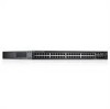
... • Reset Button • Port and System LEDs • Stack Master LED and Stack Number Display The following images show the front panels of the switch hardware. 3 Hardware Overview This section provides an overview of the switch models in the PowerConnect 7000 Series. PowerConnect 7024 with 24 10/100/1000Base-T Ports 10/100/1000Base...
... • Reset Button • Port and System LEDs • Stack Master LED and Stack Number Display The following images show the front panels of the switch hardware. 3 Hardware Overview This section provides an overview of the switch models in the PowerConnect 7000 Series. PowerConnect 7024 with 24 10/100/1000Base-T Ports 10/100/1000Base...

Page 86
Additionally, the PowerConnect 7024P and PowerConnect 7048P switches contain LEDs that provide information about the status that the LEDs indicate...configuration prior to the reset are lost. If a switch is not part of port links, power supplies, fans, stacking, and the overall system. To use the reset button, insert an unbent paper clip or similar tool into the pinhole.... panel displays the unit number for the stack member. If the M LED is off, the stack member is 1. 86 Hardware Overview Any changes made to perform a hard reset on the ...
Additionally, the PowerConnect 7024P and PowerConnect 7048P switches contain LEDs that provide information about the status that the LEDs indicate...configuration prior to the reset are lost. If a switch is not part of port links, power supplies, fans, stacking, and the overall system. To use the reset button, insert an unbent paper clip or similar tool into the pinhole.... panel displays the unit number for the stack member. If the M LED is off, the stack member is 1. 86 Hardware Overview Any changes made to perform a hard reset on the ...

Page 87
... of the PowerConnect 7000 Series switches. PC7024, PC7024F, and PC7048 Back Panel Fan Vents Dual 10G Slots for Plug-in Modules • Power Supplies • Ventilation System • Locator LED The following features: • Expansion Slots for SFP+, 10GBase-T, or Stacking/10GbE Modules ...Redundant DC Power Supply Receptacle Figure 3-9. PC7024P and PC7048P Back Panel Fan Vents AC Power Receptacle Dual 10G Slots for SFP+, 10Base-T, or External DC Power Stacking/10 GbE Modules Supply Receptacle AC Power Receptacle...
... of the PowerConnect 7000 Series switches. PC7024, PC7024F, and PC7048 Back Panel Fan Vents Dual 10G Slots for Plug-in Modules • Power Supplies • Ventilation System • Locator LED The following features: • Expansion Slots for SFP+, 10GBase-T, or Stacking/10GbE Modules ...Redundant DC Power Supply Receptacle Figure 3-9. PC7024P and PC7048P Back Panel Fan Vents AC Power Receptacle Dual 10G Slots for SFP+, 10Base-T, or External DC Power Stacking/10 GbE Modules Supply Receptacle AC Power Receptacle...

Page 88
... on the back of the switch and can be configured to reboot the switch after you do not need to operate as either 16-Gigabit stacking ports or 10-Gigabit Ethernet switch ports. Figure 3-11. 10GBase-T Module 88 Hardware Overview The following modules: • 10GBase-T module • SFP+... hot-swap support, so you install a new module. PC7048R Back Panel Fan Trays AC Power Receptacle Dual 10G Slots for SFP+, 10GBase-T, or Stacking/10GbE Modules AC Power Receptacle Expansion Slots for the PowerConnect 7000 Series switches. Figure 3-10. The plug-in module has two ports.
... on the back of the switch and can be configured to reboot the switch after you do not need to operate as either 16-Gigabit stacking ports or 10-Gigabit Ethernet switch ports. Figure 3-11. 10GBase-T Module 88 Hardware Overview The following modules: • 10GBase-T module • SFP+... hot-swap support, so you install a new module. PC7048R Back Panel Fan Trays AC Power Receptacle Dual 10G Slots for SFP+, 10GBase-T, or Stacking/10GbE Modules AC Power Receptacle Expansion Slots for the PowerConnect 7000 Series switches. Figure 3-10. The plug-in module has two ports.

Page 89
... have an internal 180-watt power supply. PC7048 PowerConnect 7048 switches have an internal 1000-watt power supply. Stacking/10 GbE Module Power Supplies PC7024 and PC7024F PowerConnect 7024 and PowerConnect 7024F switches have an internal 180-watt power supply. Figure 3-12. The additional external power supply (PowerConnect RPS720) provides 180 watts and gives full redundancy...
... have an internal 180-watt power supply. PC7048 PowerConnect 7048 switches have an internal 1000-watt power supply. Stacking/10 GbE Module Power Supplies PC7024 and PC7024F PowerConnect 7024 and PowerConnect 7024F switches have an internal 180-watt power supply. Figure 3-12. The additional external power supply (PowerConnect RPS720) provides 180 watts and gives full redundancy...

Page 93
...port, the SFP+ module has one LED per port, and the Stacking/10 GbE module does not have any LEDs. 10 Gigabit Ethernet Port LEDs Table 3-4 contains LED definitions for 10 GbE ports on the plug-in module available for PowerConnect 7000 Series switches. SFP+ Port LEDs Table 3-5 contains LED definitions ...for SFP+ port on the plug-in module available for PowerConnect 7000 Series switches. SFP+ Port LEDs Definitions LED LNK/ACT Color/Activity Green solid Green blinking Off Definition The port is sending and/or ...
...port, the SFP+ module has one LED per port, and the Stacking/10 GbE module does not have any LEDs. 10 Gigabit Ethernet Port LEDs Table 3-4 contains LED definitions for 10 GbE ports on the plug-in module available for PowerConnect 7000 Series switches. SFP+ Port LEDs Table 3-5 contains LED definitions ...for SFP+ port on the plug-in module available for PowerConnect 7000 Series switches. SFP+ Port LEDs Definitions LED LNK/ACT Color/Activity Green solid Green blinking Off Definition The port is sending and/or ...

Page 95
System LED Definitions LED Status FAN Color Definition Green solid Switch is in the PowerConnect 7000 Series. Figure 3-14. Green blinking Booting, and the diagnostics test is operating normally. Hardware Overview 95 Figure 3-14 shows the LEDs available on ...each model in progress. Green solid Fans are located on the switch model. Table 3-8. The system LEDs indicate whether the switch is the stack master and provide information about the status of the front panel. System LEDs PWR Status PWR Status PWR1 Status M MPS Fan PC7024 PC7024F PC7048 M ...
System LED Definitions LED Status FAN Color Definition Green solid Switch is in the PowerConnect 7000 Series. Figure 3-14. Green blinking Booting, and the diagnostics test is operating normally. Hardware Overview 95 Figure 3-14 shows the LEDs available on ...each model in progress. Green solid Fans are located on the switch model. Table 3-8. The system LEDs indicate whether the switch is the stack master and provide information about the status of the front panel. System LEDs PWR Status PWR Status PWR1 Status M MPS Fan PC7024 PC7024F PC7048 M ...

Page 96
...always the master. Red solid An external power supply is detected, but it is detected. M Green solid Master switch for the stack. A standalone switch is operating normally. a. Off Non-master stack unit. The PWR1 LED indicates the status of the first power supply, and the PWR2 LEDs indicates the status of the...) Off Power is detected. Off No external power supply is off or has failed. EPS Green solid External power supply is operating normally. The PowerConnect 7048R has two power supplies. RPS Green solid Redundant power supply is operating normally.
...always the master. Red solid An external power supply is detected, but it is detected. M Green solid Master switch for the stack. A standalone switch is operating normally. a. Off Non-master stack unit. The PWR1 LED indicates the status of the first power supply, and the PWR2 LEDs indicates the status of the...) Off Power is detected. Off No external power supply is off or has failed. EPS Green solid External power supply is operating normally. The PowerConnect 7048R has two power supplies. RPS Green solid Redundant power supply is operating normally.
Page 103
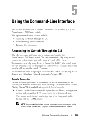
...is located on the right side of the front panel and is illuminated on the stack Master. For more information about assigning an IP address to a switch, see the Getting Started Guide available at support.dell.com/manuals. 1 Connect the DB-9 connector of switches, be able to ping ...a direct connection to the console port or by connecting to manage and monitor the PowerConnect 7000 Series switch. Using the Command-Line Interface 103 The Master LED (M) is labeled with the |O|O| symbol. NOTE: For a stack of the supplied serial cable to a management station, and connect the RJ-45 ...
...is located on the right side of the front panel and is illuminated on the stack Master. For more information about assigning an IP address to a switch, see the Getting Started Guide available at support.dell.com/manuals. 1 Connect the DB-9 connector of switches, be able to ping ...a direct connection to the console port or by connecting to manage and monitor the PowerConnect 7000 Series switch. Using the Command-Line Interface 103 The Master LED (M) is labeled with the |O|O| symbol. NOTE: For a stack of the supplied serial cable to a management station, and connect the RJ-45 ...
Page 104
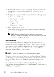
... format - 8 data bits • Parity - After the boot process completes, the console> prompt displays, and you can use any Telnet client on the switch (or stack). However, if an authentication method has been configured for example, COM 1) to connect to the local device through a TCP/IP protocol network. The switch supports...
... format - 8 data bits • Parity - After the boot process completes, the console> prompt displays, and you can use any Telnet client on the switch (or stack). However, if an authentication method has been configured for example, COM 1) to connect to the local device through a TCP/IP protocol network. The switch supports...


