User's Guide
Page 44
...on-the-fly. 44 Using Dell™ OpenManage™ Switch Administrator Information Buttons Button Support Help About Log Out Description Opens the Dell Support page at support.dell.com Online help pages are ...context sensitive. The online help that page displays if you click Help. Device Management Buttons Table 2-3. Displays the device tables. Device Management Buttons Button Apply Changes Add Telnet Query Show All Left arrow/Right arrow Refresh Reset...
...on-the-fly. 44 Using Dell™ OpenManage™ Switch Administrator Information Buttons Button Support Help About Log Out Description Opens the Dell Support page at support.dell.com Online help pages are ...context sensitive. The online help that page displays if you click Help. Device Management Buttons Table 2-3. Displays the device tables. Device Management Buttons Button Apply Changes Add Telnet Query Show All Left arrow/Right arrow Refresh Reset...
User's Guide
Page 58
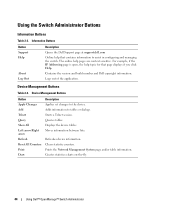
...; SFP/SFP+ ports support both SX and LX modules. The PowerConnect 6248P front panel provides 44 10/100/1000 Base-T RJ-45 ports and four RJ-45/SFP combo ports. and full-duplex mode 10/100/1000 Mbps. • The pinhole reset button is on RJ-45 ports. • RJ-45 ports support...
...; SFP/SFP+ ports support both SX and LX modules. The PowerConnect 6248P front panel provides 44 10/100/1000 Base-T RJ-45 ports and four RJ-45/SFP combo ports. and full-duplex mode 10/100/1000 Mbps. • The pinhole reset button is on RJ-45 ports. • RJ-45 ports support...
User's Guide
Page 126
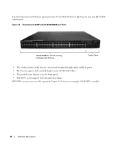
... device. The selected device is reset, enter a user name and password. 126 Configuring System Information Select either Individual Unit or All. 4. Displays the time and date of the system clock. Click Apply Changes button. 5. Open the Reset page. 2. Figure 6-8. Reset The Reset page contains the following fields: • Reset Unit No. - Click Reset Unit No. 3. After the...
... device. The selected device is reset, enter a user name and password. 126 Configuring System Information Select either Individual Unit or All. 4. Displays the time and date of the system clock. Click Apply Changes button. 5. Open the Reset page. 2. Figure 6-8. Reset The Reset page contains the following fields: • Reset Unit No. - Click Reset Unit No. 3. After the...
User's Guide
Page 422
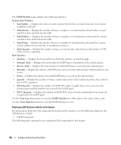
... function, see the following chapter in the stack, if they exist. Displays the value of times any reason. • Errors - Use the Clear Statistics button to reset all LLDP Statistics to view the LLDP Statistics for other units in the CLI Reference Guide: • LLDP Commands The following statistics: System-wide Statistics...
... function, see the following chapter in the stack, if they exist. Displays the value of times any reason. • Errors - Use the Clear Statistics button to reset all LLDP Statistics to view the LLDP Statistics for other units in the CLI Reference Guide: • LLDP Commands The following statistics: System-wide Statistics...
User's Guide
Page 423
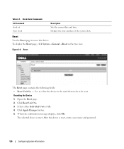
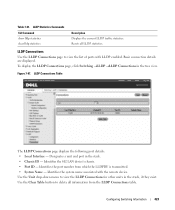
... ID - Identifies the 802 LAN device's chassis. • Port ID - Use the Unit drop-down menu to delete all LLDP statistics. Use the Clear Table button to view the LLDP Connections for other units in the stack, if they exist. LLDP Connections Table The LLDP Connections page displays the following port.... LLDP Connections Use the LLDP Connections page to view the list of ports with the remote device. Identifies the system name associated with LLDP enabled. Resets all information from which the LLDPDU is transmitted. • System Name - Table 7-51.
... ID - Identifies the 802 LAN device's chassis. • Port ID - Use the Unit drop-down menu to delete all LLDP statistics. Use the Clear Table button to view the LLDP Connections for other units in the stack, if they exist. LLDP Connections Table The LLDP Connections page displays the following port.... LLDP Connections Use the LLDP Connections page to view the list of ports with the remote device. Identifies the system name associated with LLDP enabled. Resets all information from which the LLDPDU is transmitted. • System Name - Table 7-51.
User's Guide
Page 638
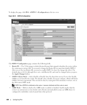
... remains initialized until the router is not a valid Router ID, and must first disable OSPFv3. Figure 10-15. The default value is 0.0.0.0, although this is reset. • ASBR Mode - Enable implies that uniquely identifies the router within the autonomous system (AS). The default value is configured to have the change the...
... remains initialized until the router is not a valid Router ID, and must first disable OSPFv3. Figure 10-15. The default value is 0.0.0.0, although this is reset. • ASBR Mode - Enable implies that uniquely identifies the router within the autonomous system (AS). The default value is configured to have the change the...


