Command Line Interface Guide
Page 1166
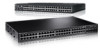
... Configuration This command has no default configuration. console#show fiber-ports optical-transceiver command in Privileged EXEC mode to the SFP combo ports and XFP ports (not the ports on the SFP+ plug-in module). show fiber-ports optical-transceiver Use the show fiber-ports optical-transceiver Port TX Temp Voltage Current...
... Configuration This command has no default configuration. console#show fiber-ports optical-transceiver command in Privileged EXEC mode to the SFP combo ports and XFP ports (not the ports on the SFP+ plug-in module). show fiber-ports optical-transceiver Use the show fiber-ports optical-transceiver Port TX Temp Voltage Current...
User's Guide
Page 4
Device Management Buttons 44 Check Boxes 45 Defining Fields 45 Accessing the Switch Through the CLI 45 Console Connection 46 Telnet Connection 46 Using the CLI 46 Command Mode Overview 46 User EXEC Mode 47 Privileged EXEC Mode 47 Global Configuration Mode 48 Interface Configuration Mode 48 3 Cable and Port Information Overview 49 Ethernet Interface 50 SFP Interfaces 51 Bay 1 and Bay 2 Interfaces 52 Serial Cable Connection 52 Connecting the Switch to a Terminal 52 4
Device Management Buttons 44 Check Boxes 45 Defining Fields 45 Accessing the Switch Through the CLI 45 Console Connection 46 Telnet Connection 46 Using the CLI 46 Command Mode Overview 46 User EXEC Mode 47 Privileged EXEC Mode 47 Global Configuration Mode 48 Interface Configuration Mode 48 3 Cable and Port Information Overview 49 Ethernet Interface 50 SFP Interfaces 51 Bay 1 and Bay 2 Interfaces 52 Serial Cable Connection 52 Connecting the Switch to a Terminal 52 4
User's Guide
Page 5
... Supplies 62 Ventilation System 62 Stacking 62 Stacking Standby 63 LED Definitions 64 SFP Port LEDs 64 SFP+ Port LEDs 65 XFP Module Port LEDs 65 10/100/1000 Base-T Port LEDs 65 System LEDs 67 Stacking LEDs 68 5 Configuring Dell PowerConnect Overview 71 Starting the CLI 72 General Configuration Information 74 Terminal Connection...
... Supplies 62 Ventilation System 62 Stacking 62 Stacking Standby 63 LED Definitions 64 SFP Port LEDs 64 SFP+ Port LEDs 65 XFP Module Port LEDs 65 10/100/1000 Base-T Port LEDs 65 System LEDs 67 Stacking LEDs 68 5 Configuring Dell PowerConnect Overview 71 Starting the CLI 72 General Configuration Information 74 Terminal Connection...

User's Guide
Page 19
...with hot swappable stack members. The Dell PowerConnect 6224 switch supports 24 1000Base-T copper ports and 4 "combo" ports for PoE capability. The Dell PowerConnect 6248P adds support for RJ-45 or SFP interfaces. The Dell PowerConnect 6224F switch supports 24 1000Base-FX SFP ports and 4 "combo" ports ...; High availability with the firmware available on the Dell Support website, support.dell.com. NOTE: Before proceeding, read the release notes for RJ-45 or SFP interfaces. The topics covered in this product. The Dell PowerConnect 6248 supports 48 1000Base-T copper ports and 4 ...
...with hot swappable stack members. The Dell PowerConnect 6224 switch supports 24 1000Base-T copper ports and 4 "combo" ports for PoE capability. The Dell PowerConnect 6248P adds support for RJ-45 or SFP interfaces. The Dell PowerConnect 6224F switch supports 24 1000Base-FX SFP ports and 4 "combo" ports ...; High availability with the firmware available on the Dell Support website, support.dell.com. NOTE: Before proceeding, read the release notes for RJ-45 or SFP interfaces. The topics covered in this product. The Dell PowerConnect 6248 supports 48 1000Base-T copper ports and 4 ...
User's Guide
Page 49
Stations are connected to the switch's ports through the physical interface ports on the front panel. The topics covered in this section include: • Ethernet Interface • SFP Interfaces • Bay 1 and Bay 2 Interfaces • Serial Cable Connection • Power Connection Cable and Port Information 49 3 Cable and Port Information Overview This section describes the switch's physical interfaces and provides information about cable connections. For each station, the appropriate mode (Half-Duplex, Full-Duplex, Auto) is set.
Stations are connected to the switch's ports through the physical interface ports on the front panel. The topics covered in this section include: • Ethernet Interface • SFP Interfaces • Bay 1 and Bay 2 Interfaces • Serial Cable Connection • Power Connection Cable and Port Information 49 3 Cable and Port Information Overview This section describes the switch's physical interfaces and provides information about cable connections. For each station, the appropriate mode (Half-Duplex, Full-Duplex, Auto) is set.
User's Guide
Page 51
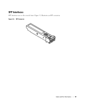
SFP Connector Cable and Port Information 51 Figure 3-2 illustrates an SFP connector. Figure 3-2. SFP Interfaces SFP interfaces are on the console front.
SFP Connector Cable and Port Information 51 Figure 3-2 illustrates an SFP connector. Figure 3-2. SFP Interfaces SFP interfaces are on the console front.

User's Guide
Page 52
...connect the switch to the serial port of the Master switch. Bay 1 and Bay 2 PowerConnect 6200 Series 10 Gb Slots Serial Cable Connection You can operate at 10 Gbps when supporting optional SFP+, CX4, XFP, and 10GBase-T modules. Figure 3-3. The switch's serial cable is a female... to Console 52 Cable and Port Information Bay 1 and Bay 2 Interfaces The Dell™ PowerConnect™ 6200series switches support dual 10 Gb slot interfaces...
...connect the switch to the serial port of the Master switch. Bay 1 and Bay 2 PowerConnect 6200 Series 10 Gb Slots Serial Cable Connection You can operate at 10 Gbps when supporting optional SFP+, CX4, XFP, and 10GBase-T modules. Figure 3-3. The switch's serial cable is a female... to Console 52 Cable and Port Information Bay 1 and Bay 2 Interfaces The Dell™ PowerConnect™ 6200series switches support dual 10 Gb slot interfaces...

User's Guide
Page 56
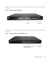
...-sensing Full-Duplex RJ-45 Ports 56 Hardware Description Combo Ports Figure 4-1. PowerConnect 6248 with four RJ-45/SFP combo ports that have an auto-sensing mode for speed, flow control, and duplex mode. Figure 4-2. PowerConnect 6224 with 24 10/100/1000 Base-T Ports 10/100/1000Base-T Auto-sensing Full... Duplex RJ-45 Ports Combo Ports The PowerConnect 6248 front panel provides 48 10...
...-sensing Full-Duplex RJ-45 Ports 56 Hardware Description Combo Ports Figure 4-1. PowerConnect 6248 with four RJ-45/SFP combo ports that have an auto-sensing mode for speed, flow control, and duplex mode. Figure 4-2. PowerConnect 6224 with 24 10/100/1000 Base-T Ports 10/100/1000Base-T Auto-sensing Full... Duplex RJ-45 Ports Combo Ports The PowerConnect 6248 front panel provides 48 10...
User's Guide
Page 57
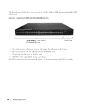
The PowerConnect 6224F front panel provides 24 10/100/1000M Base-FX SFP ports and four RJ-45/SFP combo ports. Figure 4-3. PowerConnect 6224P with 24 SFP Ports SFP Ports Combo Ports The PowerConnect 6224P front panel provides 24 10/100/1000M Base-T RJ-45 ports and four RJ-45/SFP combo ports. Figure 4-4. PowerConnect 6224F with 24 10/100/1000 Base-T Ports 10/100/1000Base-T Auto-sensing Full Duplex RJ-45 Ports Combo Ports Hardware Description 57
The PowerConnect 6224F front panel provides 24 10/100/1000M Base-FX SFP ports and four RJ-45/SFP combo ports. Figure 4-3. PowerConnect 6224P with 24 SFP Ports SFP Ports Combo Ports The PowerConnect 6224P front panel provides 24 10/100/1000M Base-T RJ-45 ports and four RJ-45/SFP combo ports. Figure 4-4. PowerConnect 6224F with 24 10/100/1000 Base-T Ports 10/100/1000Base-T Auto-sensing Full Duplex RJ-45 Ports Combo Ports Hardware Description 57
User's Guide
Page 58
... • The switch automatically detects crossed and straight-through cables on the front panel. • SFP/SFP+ ports support both SX and LX modules. SFP/SFP+ transceivers are sold separately. Figure 4-5. The PowerConnect 6248P front panel provides 44 10/100/1000 Base-T RJ-45 ports and four RJ-45.../SFP combo ports. and full-duplex mode 10/100/1000 Mbps. • The pinhole reset button is on ...
... • The switch automatically detects crossed and straight-through cables on the front panel. • SFP/SFP+ ports support both SX and LX modules. SFP/SFP+ transceivers are sold separately. Figure 4-5. The PowerConnect 6248P front panel provides 44 10/100/1000 Base-T RJ-45 ports and four RJ-45.../SFP combo ports. and full-duplex mode 10/100/1000 Mbps. • The pinhole reset button is on ...
User's Guide
Page 60
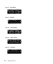
Figure 4-8. Stacking Module Figure 4-9. SFP+ Module 60 Hardware Description XFP Module Figure 4-10. 10 GbE CX4 Module Figure 4-11. 10GBase-T Module Figure 4-12.
Figure 4-8. Stacking Module Figure 4-9. SFP+ Module 60 Hardware Description XFP Module Figure 4-10. 10 GbE CX4 Module Figure 4-11. 10GBase-T Module Figure 4-12.

User's Guide
Page 64
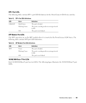
Figure 4-14. SFP Port LEDs Table 4-1 contains SFP port LED definitions. SFP Port LEDs Definitions LED LNK/ACT Color Solid Green Flashing Green Off Definition The port is sending and/or receiving network traffic. The port is linked. LED Definitions The front panel contains light emitting diodes (LEDs) that are above each SFP port. Table 4-1. The port is not linked. 64 Hardware Description Figure 4-15. Front Panel LEDs SFP Port LEDs Figure 4-15 illustrates the SFP port LEDs that indicate the status of links, power supplies, fans, system diagnostics, and the stack.
Figure 4-14. SFP Port LEDs Table 4-1 contains SFP port LED definitions. SFP Port LEDs Definitions LED LNK/ACT Color Solid Green Flashing Green Off Definition The port is sending and/or receiving network traffic. The port is linked. LED Definitions The front panel contains light emitting diodes (LEDs) that are above each SFP port. Table 4-1. The port is not linked. 64 Hardware Description Figure 4-15. Front Panel LEDs SFP Port LEDs Figure 4-15 illustrates the SFP port LEDs that indicate the status of links, power supplies, fans, system diagnostics, and the stack.
User's Guide
Page 65
... Definitions LED LNK/ACT Color Solid Green Flashing Green Off Definition The port is linked. The following table contains SFP+ port LED definitions for the PowerConnect 6200 Series switches. Table 4-3. XFP Module Port LEDs Definitions LED Color Definition XFP Green The port is linked. The ...and/or receiving network traffic. Hardware Description 65 SFP+ Port LEDs The following table contains XFP port LED definitions. XFP Module Port LEDs The XFP connectors are on the XFP module when it is inserted in the PowerConnect 6200 Series. The following figure illustrates the 10...
... Definitions LED LNK/ACT Color Solid Green Flashing Green Off Definition The port is linked. The following table contains SFP+ port LED definitions for the PowerConnect 6200 Series switches. Table 4-3. XFP Module Port LEDs Definitions LED Color Definition XFP Green The port is linked. The ...and/or receiving network traffic. Hardware Description 65 SFP+ Port LEDs The following table contains XFP port LED definitions. XFP Module Port LEDs The XFP connectors are on the XFP module when it is inserted in the PowerConnect 6200 Series. The following figure illustrates the 10...
User's Guide
Page 155
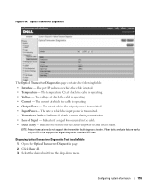
... unit from the drop-down menu. Optical Transceiver Diagnostics The Optical Transceiver Diagnostics page contains the following fields: • Interface - The port IP address on SFPs that support the digital diagnostic standard SFF-4872. The voltage at which the cable is tested. • Temperature - Indicates if a signal loss occurred in the...
... unit from the drop-down menu. Optical Transceiver Diagnostics The Optical Transceiver Diagnostics page contains the following fields: • Interface - The port IP address on SFPs that support the digital diagnostic standard SFF-4872. The voltage at which the cable is tested. • Temperature - Indicates if a signal loss occurred in the...
Getting Started Guide
Page 6
3 Managing a Stack Master and Member Switches 16 Stack Startup 16 Topology Discovery 16 Auto Stack ID Assignment 16 Firmware Version Checking 16 System Initialization 17 CLI/ Telnet/ Web Interface 17 Insertion and Removal of Switches 17 Operating as Standalone Switch 17 Stack ID Renumbering 17 User Controls 18 4 Front Panels and LEDs Front Panels 19 LEDs 20 Systems LEDs 20 RJ-45 LEDs (PoE 21 XFP LED 21 SFP LED 21 4 Contents
3 Managing a Stack Master and Member Switches 16 Stack Startup 16 Topology Discovery 16 Auto Stack ID Assignment 16 Firmware Version Checking 16 System Initialization 17 CLI/ Telnet/ Web Interface 17 Insertion and Removal of Switches 17 Operating as Standalone Switch 17 Stack ID Renumbering 17 User Controls 18 4 Front Panels and LEDs Front Panels 19 LEDs 20 Systems LEDs 20 RJ-45 LEDs (PoE 21 XFP LED 21 SFP LED 21 4 Contents
Getting Started Guide
Page 23
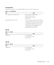
...: Port link/activity Right (POE Model) - XFP LED LED Single color: State • Green Solid: Link • Green Blinking: Activity • Off: No Link SFP LED Table 1-4. SFP LED LED Single color: State • Green Solid: Link • Green Blinking: Activity • Off: No Link Getting Started Guide 21 Dual color: State...
...: Port link/activity Right (POE Model) - XFP LED LED Single color: State • Green Solid: Link • Green Blinking: Activity • Off: No Link SFP LED Table 1-4. SFP LED LED Single color: State • Green Solid: Link • Green Blinking: Activity • Off: No Link Getting Started Guide 21 Dual color: State...
Getting Started Guide
Page 124
3 136 137 137 137 137 137 CLI/ Telnet/ Web 138 138 138 138 139 4 LED 141 LED 142 LED 142 LED RJ-45 (PoE 143 LED XFP 143 LED SFP 143 122
3 136 137 137 137 137 137 CLI/ Telnet/ Web 138 138 138 138 139 4 LED 141 LED 142 LED 142 LED RJ-45 (PoE 143 LED XFP 143 LED SFP 143 122
Configuration Guide
Page 25
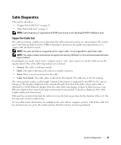
... Reflectometry (TDR) technology to determine the quality and characteristics of the test. The command also returns a cable length estimate if this feature is supported on SFP/XFP ports but not on the specified port. Unknown is displayed if the cable length could not be determined. To view cable status information for...
... Reflectometry (TDR) technology to determine the quality and characteristics of the test. The command also returns a cable length estimate if this feature is supported on SFP/XFP ports but not on the specified port. Unknown is displayed if the cable length could not be determined. To view cable status information for...
Configuration Guide
Page 27
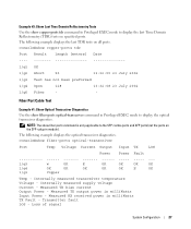
... voltage Current - Example #3: Show Last Time Domain Reflectometry Tests Use the show fiber ports command is only applicable to the SFP combo ports and XFP ports (not the ports on the SFP+ plug-in Privileged EXEC mode to display the last Time Domain Reflectometry (TDR) tests on specified ports. Loss of signal...
... voltage Current - Example #3: Show Last Time Domain Reflectometry Tests Use the show fiber ports command is only applicable to the SFP combo ports and XFP ports (not the ports on the SFP+ plug-in Privileged EXEC mode to display the last Time Domain Reflectometry (TDR) tests on specified ports. Loss of signal...


