Command Line Interface (CLI) Guide (.htm)
Page 275
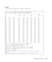
Transmitter fault LOS - Not Supported, W - Internally measured supply voltage Current - Measured TX output power in milliWatts TX Fault - Internally measured transceiver temperature Voltage - Measured TX bias current Output Power - Warning, E - Loss of signal Data Ready - Not Available, N/S - Error PHY Diagnostics Commands 275 Examples The following example displays the optical transceiver diagnostics. Measured RX received...
Transmitter fault LOS - Not Supported, W - Internally measured supply voltage Current - Measured TX output power in milliWatts TX Fault - Internally measured transceiver temperature Voltage - Measured TX bias current Output Power - Warning, E - Loss of signal Data Ready - Not Available, N/S - Error PHY Diagnostics Commands 275 Examples The following example displays the optical transceiver diagnostics. Measured RX received...
Command Line Interface (CLI) Guide (.htm)
Page 276
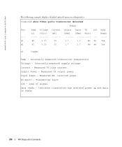
... ----Yes Yes g3 Copper Temp - Internally measured supply voltage. Tx Fault - Voltage - Input Power - Loss of signal Data ready - Indicates transceiver has achieved power up and data is ready. 276 PHY Diagnostics Commands Output Power - Current - Measured RX received power. Internally measured transceiver temperature. www.dell.com | support.dell.com The following example displays detailed optical transceiver...
... ----Yes Yes g3 Copper Temp - Internally measured supply voltage. Tx Fault - Voltage - Input Power - Loss of signal Data ready - Indicates transceiver has achieved power up and data is ready. 276 PHY Diagnostics Commands Output Power - Current - Measured RX received power. Internally measured transceiver temperature. www.dell.com | support.dell.com The following example displays detailed optical transceiver...
Command Line Interface (CLI) Guide (.htm)
Page 429
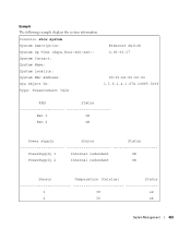
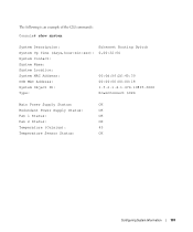
Console> show system System Description: Ethernet Switch System Up Time (days,hour:min:sec): 0,00:00:17 System Contact: System Name: System Location: System MAC Address: 00:00:b0:00:00:00 Sys Object ID: 1.3.6.1.4.1.674.10895.3006 Type: PowerConnect 3424 FAN Status Fan 1 OK Fan 2 OK Power supply Source Status PowerSupply 1 Internal redundant OK PowerSupply 2 Internal redundant OK Sensor Temperature (Celsius) Status 1 38 ok 2 36 ok System Management 429 Example The following example displays the system information.
Console> show system System Description: Ethernet Switch System Up Time (days,hour:min:sec): 0,00:00:17 System Contact: System Name: System Location: System MAC Address: 00:00:b0:00:00:00 Sys Object ID: 1.3.6.1.4.1.674.10895.3006 Type: PowerConnect 3424 FAN Status Fan 1 OK Fan 2 OK Power supply Source Status PowerSupply 1 Internal redundant OK PowerSupply 2 Internal redundant OK Sensor Temperature (Celsius) Status 1 38 ok 2 36 ok System Management 429 Example The following example displays the system information.
User's Guide (.htm)
Page 3
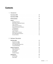
Contents 1 Introduction PowerConnect 6024 23 PowerConnect 6024F 24 CLI Documentation 24 Features 24 Port Based Features 24 MAC Address Supported Features 26 Layer 2 Features 26 VLAN Supported Features 27 Spanning Tree ... Features 31 Device Management Features 32 Security Features 34 2 Hardware Description Ports Description 37 PowerConnect 6024 37 PowerConnect 6024F 38 Out-of-Band Management Port 38 Console (RS-232) Port 38 Hardware Components 39 Physical Dimensions 39 Power Supplies 39 Reset Button 40 Ventilation System 40 LED Definitions 40 SFP Port LEDs 41 System...
Contents 1 Introduction PowerConnect 6024 23 PowerConnect 6024F 24 CLI Documentation 24 Features 24 Port Based Features 24 MAC Address Supported Features 26 Layer 2 Features 26 VLAN Supported Features 27 Spanning Tree ... Features 31 Device Management Features 32 Security Features 34 2 Hardware Description Ports Description 37 PowerConnect 6024 37 PowerConnect 6024F 38 Out-of-Band Management Port 38 Console (RS-232) Port 38 Hardware Components 39 Physical Dimensions 39 Power Supplies 39 Reset Button 40 Ventilation System 40 LED Definitions 40 SFP Port LEDs 41 System...
User's Guide (.htm)
Page 13
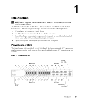
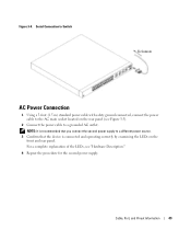
...; High availability with hot swappable power supplies and cooling fans PowerConnect 6024 The PowerConnect 6024 provides 24 10/100/1000 Base-T RJ-45 ports with eight SFP combo ports that extends the Dell PowerConnect LAN switching product range. The Dell™ PowerConnect™ 6024/6024F is a standalone Layer 3 switch...8226; Support for all data-communication requirements for this product. You can download the release notes from support.dell.com. Figure 1-1. Introduction NOTICE: Before proceeding, read the release notes for a multi-layer switch, including a full suite of ...
...; High availability with hot swappable power supplies and cooling fans PowerConnect 6024 The PowerConnect 6024 provides 24 10/100/1000 Base-T RJ-45 ports with eight SFP combo ports that extends the Dell PowerConnect LAN switching product range. The Dell™ PowerConnect™ 6024/6024F is a standalone Layer 3 switch...8226; Support for all data-communication requirements for this product. You can download the release notes from support.dell.com. Figure 1-1. Introduction NOTICE: Before proceeding, read the release notes for a multi-layer switch, including a full suite of ...
User's Guide (.htm)
Page 29
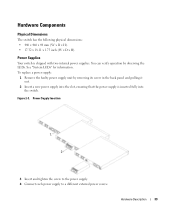
See "System LEDs" for information. Power Supply Insertion 1 2 3 Insert and tighten the screw to the power supply. 4 Connect each power supply to a different external power source. To replace a power supply: 1 Remove the faulty power supply unit by observing the LEDs. Hardware Description 39 Hardware Components Physical Dimensions The switch has the following physical ...You can verify operation by removing its screw in the back panel and pulling it out. 2 Insert a new power supply into the switch. Power Supplies Your switch is inserted fully into the slot, ensuring that the...
See "System LEDs" for information. Power Supply Insertion 1 2 3 Insert and tighten the screw to the power supply. 4 Connect each power supply to a different external power source. To replace a power supply: 1 Remove the faulty power supply unit by observing the LEDs. Hardware Description 39 Hardware Components Physical Dimensions The switch has the following physical ...You can verify operation by removing its screw in the back panel and pulling it out. 2 Insert a new power supply into the switch. Power Supplies Your switch is inserted fully into the slot, ensuring that the...
User's Guide (.htm)
Page 30
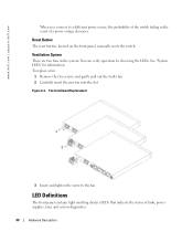
... contains light emitting diodes (LED) that indicate the status of links, power supplies, fans, and system diagnostics. 40 Hardware Description See "System LEDs" for information. Figure 2-4. Ventilation System There are two fans in the event of a power outage decreases. www.dell.com | support.dell.com When you connect to the fan. Reset Button The reset...
... contains light emitting diodes (LED) that indicate the status of links, power supplies, fans, and system diagnostics. 40 Hardware Description See "System LEDs" for information. Figure 2-4. Ventilation System There are two fans in the event of a power outage decreases. www.dell.com | support.dell.com When you connect to the fan. Reset Button The reset...
User's Guide (.htm)
Page 32
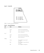
... active. System LEDs The system LEDs, located on the left side of the front panel, provide information about the power supplies, fans, thermal conditions, and diagnostics. The port is not linked. Figure 2-7 illustrates the System LEDs. 42 Hardware Description www.dell.com | support.dell.com Table 2-2 contains 10/100/1000 Base-T port LED definitions.
... active. System LEDs The system LEDs, located on the left side of the front panel, provide information about the power supplies, fans, thermal conditions, and diagnostics. The port is not linked. Figure 2-7 illustrates the System LEDs. 42 Hardware Description www.dell.com | support.dell.com Table 2-2 contains 10/100/1000 Base-T port LED definitions.
User's Guide (.htm)
Page 33
Fan 1 is present, but not operating. Fan 1 is present and operating. Power Supply 1 is not present. Figure 2-7. Hardware Description 43 Fan 2 is present and operating. Table 2-3. Power Supply 1 is present and operating. System LED Definitions LED Fan 1 Fan 2 PWR1 Color Green Red Off Green Red Off Green Red Off Definition Fan 1 is present, but not operating. Power Supply 1 is not present. Fan 2 is not present. System LEDs Table 2-3 contains system LED definitions. Fan 2 is present, but not operating.
Fan 1 is present, but not operating. Fan 1 is present and operating. Power Supply 1 is not present. Figure 2-7. Hardware Description 43 Fan 2 is present and operating. Table 2-3. Power Supply 1 is present and operating. System LED Definitions LED Fan 1 Fan 2 PWR1 Color Green Red Off Green Red Off Green Red Off Definition Fan 1 is present, but not operating. Power Supply 1 is not present. Fan 2 is not present. System LEDs Table 2-3 contains system LED definitions. Fan 2 is present, but not operating.
User's Guide (.htm)
Page 34
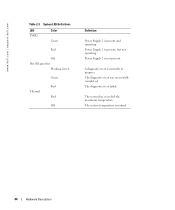
Power Supply 2 is present, but not operating. The system has exceeded the maximum temperature. Power Supply 2 is not present. A diagnostics test is present and operating. The diagnostics test was successfully completed. The diagnostics test failed. System LED Definitions LED PWR2 Color Green Red Off Dia (Diagnostic) Flashing Green Green Red Thermal Red Off Definition Power Supply 2 is currently in progress. The system temperature is normal. 44 Hardware Description www.dell.com | support.dell.com Table 2-3.
Power Supply 2 is present, but not operating. The system has exceeded the maximum temperature. Power Supply 2 is not present. A diagnostics test is present and operating. The diagnostics test was successfully completed. The diagnostics test failed. System LED Definitions LED PWR2 Color Green Red Off Dia (Diagnostic) Flashing Green Green Red Thermal Red Off Definition Power Supply 2 is currently in progress. The system temperature is normal. 44 Hardware Description www.dell.com | support.dell.com Table 2-3.
User's Guide (.htm)
Page 37
... Receiver ground (common with transmitter ground) 11 Receiver ground (common with receiver ground). AC coupled. 14 Receiver ground (common with transmitter ground) 15 Receiver power supply 16 Transmitter power supply 17 Transmitter ground (common with receiver ground) 18 Transmitter non-inverted data in 19 Transmitter inverted data in 20 Transmitter ground (common with transmitter...
... Receiver ground (common with transmitter ground) 11 Receiver ground (common with receiver ground). AC coupled. 14 Receiver ground (common with transmitter ground) 15 Receiver power supply 16 Transmitter power supply 17 Transmitter ground (common with receiver ground) 18 Transmitter non-inverted data in 19 Transmitter inverted data in 20 Transmitter ground (common with transmitter...
User's Guide (.htm)
Page 39
.... For a complete explanation of the LEDs, see Figure 3-5). 2 Connect the power cable to a different power source. 3 Confirm that the device is connected and operating correctly by examining the LEDs on the rear panel (see "Hardware Description." 4 Repeat the procedure for the second power supply. Cable, Port, and Pinout Information 49 NOTE: It is recommended...
.... For a complete explanation of the LEDs, see Figure 3-5). 2 Connect the power cable to a different power source. 3 Confirm that the device is connected and operating correctly by examining the LEDs on the rear panel (see "Hardware Description." 4 Repeat the procedure for the second power supply. Cable, Port, and Pinout Information 49 NOTE: It is recommended...
User's Guide (.htm)
Page 53
.... POST runs every time the device is initialized and checks hardware components to determine if the device is connected to the terminal. 2 Connect the power supply to the serial port (cross-cable) in 2 seconds - Configuring the Switch 63 To boot the switch, perform the following steps: 1 Ensure...address for the switch for downloading embedded software and configuring the device: • ASCII terminal (or emulation) connected to the switch. 3 Power on the switch. The boot process runs approximately 30 seconds. If POST passes successfully, a valid executable image is loaded into RAM.
.... POST runs every time the device is initialized and checks hardware components to determine if the device is connected to the terminal. 2 Connect the power supply to the serial port (cross-cable) in 2 seconds - Configuring the Switch 63 To boot the switch, perform the following steps: 1 Ensure...address for the switch for downloading embedded software and configuring the device: • ASCII terminal (or emulation) connected to the switch. 3 Power on the switch. The boot process runs approximately 30 seconds. If POST passes successfully, a valid executable image is loaded into RAM.

User's Guide (.htm)
Page 96
...dell.com | support.dell.com Figure 6-4. The power supply is currently not present. Not Present-The power supply is not operating normally. The PowerConnect 6024/6024F has two fans. - The fan is currently not present. Not Present-A fan is operating normally. - Viewing System Health Information Using the CLI Commands The following fields: Power Supply-The power supply...CLI Command show system Description Displays system information. 106 Configuring System Information The power supply is not operating normally. Fan-Indicates the fan status. The fan is operating normally...
...dell.com | support.dell.com Figure 6-4. The power supply is currently not present. Not Present-The power supply is not operating normally. The PowerConnect 6024/6024F has two fans. - The fan is currently not present. Not Present-A fan is operating normally. - Viewing System Health Information Using the CLI Commands The following fields: Power Supply-The power supply...CLI Command show system Description Displays system information. 106 Configuring System Information The power supply is not operating normally. Fan-Indicates the fan status. The fan is operating normally...
User's Guide (.htm)
Page 97
The following is an example of the CLI commands: Console# show system System Description: System Up Time (days,hour:min:sec): System Contact: System Name: System Location: System MAC Address: OOB MAC Address: System Object ID: Type: Ethernet Routing Switch 0,00:32:04 00:0d:56:2f:45:30 00:00:00:00:00:18 1.3.6.1.4.1.674.10895.3000 PowerConnect 6024 Main Power Supply Status: OK Redundant Power Supply Status: OK Fan 1 Status: OK Fan 2 Status: OK Temperature (Celsius): 45 Temperature Sensor Status: OK Configuring System Information 107
The following is an example of the CLI commands: Console# show system System Description: System Up Time (days,hour:min:sec): System Contact: System Name: System Location: System MAC Address: OOB MAC Address: System Object ID: Type: Ethernet Routing Switch 0,00:32:04 00:0d:56:2f:45:30 00:00:00:00:00:18 1.3.6.1.4.1.674.10895.3000 PowerConnect 6024 Main Power Supply Status: OK Redundant Power Supply Status: OK Fan 1 Status: OK Fan 2 Status: OK Temperature (Celsius): 45 Temperature Sensor Status: OK Configuring System Information 107
User's Guide (.htm)
Page 160
...for accessing the device. To open the Management Security page, click System→Management Security in milliWatts • Input Power - www.dell.com | support.dell.com Performing Fiber Optic Cable Tests Using CLI Commands The following columns appear on SFPs that support the digital diagnostic standard...diagnostics. Transmitter fault NOTE: Finisar transceivers do not support the transmitter fault diagnostic testing. • LOS - Warning, E - Internally measured supply voltage • Current - Not Supported, W - Measured TX output power in the tree view. Measured RX received...
...for accessing the device. To open the Management Security page, click System→Management Security in milliWatts • Input Power - www.dell.com | support.dell.com Performing Fiber Optic Cable Tests Using CLI Commands The following columns appear on SFPs that support the digital diagnostic standard...diagnostics. Transmitter fault NOTE: Finisar transceivers do not support the transmitter fault diagnostic testing. • LOS - Warning, E - Internally measured supply voltage • Current - Not Supported, W - Measured TX output power in the tree view. Measured RX received...


