Command Line Interface (CLI) Guide (.htm)
Page 380
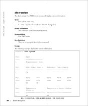
Syntax show system Unit ---1 Type PowerConnect 3424 Unit ---1 Main Power Supply OK Redundant Power Supply Unit ---1 Fan1 ---OK Fan2 ---OK Fan3 ---- Example The following example displays the system information. ... User Guidelines There are no default configuration. Console> show system [unit unit] • unit- Unit Temperature (Celsius) Temperature Sensor Status ---- 1 30 OK DELL CONFIDENTIAL - www.dell.com | support.dell.com show system The show system User EXEC mode command displays system information. Fan5 ---- FOR PROOF ONLY 380 System Management
Syntax show system Unit ---1 Type PowerConnect 3424 Unit ---1 Main Power Supply OK Redundant Power Supply Unit ---1 Fan1 ---OK Fan2 ---OK Fan3 ---- Example The following example displays the system information. ... User Guidelines There are no default configuration. Console> show system [unit unit] • unit- Unit Temperature (Celsius) Temperature Sensor Status ---- 1 30 OK DELL CONFIDENTIAL - www.dell.com | support.dell.com show system The show system User EXEC mode command displays system information. Fan5 ---- FOR PROOF ONLY 380 System Management
User's Guide (.htm)
Page 5
4 Configuring PowerConnect 3424/P and 3448/P Configuration Procedures 59 Booting the Switch 60 Initial Configuration 61 Advanced Configuration 65 Retrieving an IP Address From a DHCP Server 65 Receiving an ... TFTP Server 73 Port Default Settings 76 Auto-Negotiation 76 MDI/MDIX 76 Flow Control 76 Back Pressure 76 Switching Port Default Settings 77 5 Using Dell OpenManage Switch Administrator Starting the Application 79 Understanding the Interface 79 Device Representation 81 Using the Switch Administrator Buttons 82 Information Buttons 82 Device Management...
4 Configuring PowerConnect 3424/P and 3448/P Configuration Procedures 59 Booting the Switch 60 Initial Configuration 61 Advanced Configuration 65 Retrieving an IP Address From a DHCP Server 65 Receiving an ... TFTP Server 73 Port Default Settings 76 Auto-Negotiation 76 MDI/MDIX 76 Flow Control 76 Back Pressure 76 Switching Port Default Settings 77 5 Using Dell OpenManage Switch Administrator Starting the Application 79 Understanding the Interface 79 Device Representation 81 Using the Switch Administrator Buttons 82 Information Buttons 82 Device Management...
User's Guide (.htm)
Page 22
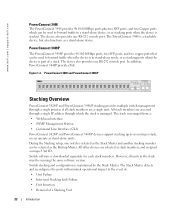
...if all units in the stack must be running the same software version. In addition, PowerConnect 3448P provides PoE. PowerConnect 3448 and PowerConnect 3448P Stacking Overview PowerConnect 3424/P and PowerConnect 3448/P stacking provides multiple switch management through which can be used to forward traffic in ...Failure • Inter-unit Stacking Link Failure • Unit Insertion • Removal of a stack. www.dell.com | support.dell.com PowerConnect 3448 The PowerConnect 3448 provides 48 10/100Mbps ports plus two SFP ports, and two Copper ports which the stack is managed...
...if all units in the stack must be running the same software version. In addition, PowerConnect 3448P provides PoE. PowerConnect 3448 and PowerConnect 3448P Stacking Overview PowerConnect 3424/P and PowerConnect 3448/P stacking provides multiple switch management through which can be used to forward traffic in ...Failure • Inter-unit Stacking Link Failure • Unit Insertion • Removal of a stack. www.dell.com | support.dell.com PowerConnect 3448 The PowerConnect 3448 provides 48 10/100Mbps ports plus two SFP ports, and two Copper ports which the stack is managed...
User's Guide (.htm)
Page 38
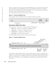
...the Reset Button which are two buttons on the front panel. RJ-45 ports designated as 1000Base-T ports • Console port - www.dell.com | support.dell.com There are fiber ports and ports G3- The Reset button does not extend beyond the unit's front panel surface, so reset by... Ports G3 G4 Stacking Ports The front panel contains 48 RJ-45 ports number 1-48. RS-232 Console based port The following figure illustrates the PowerConnect 3424 back: Figure 2-2. Ports G3- The Stack ID button is used to select the unit number. Figure 2-3. Designated as stacking ports, or used...
...the Reset Button which are two buttons on the front panel. RJ-45 ports designated as 1000Base-T ports • Console port - www.dell.com | support.dell.com There are fiber ports and ports G3- The Reset button does not extend beyond the unit's front panel surface, so reset by... Ports G3 G4 Stacking Ports The front panel contains 48 RJ-45 ports number 1-48. RS-232 Console based port The following figure illustrates the PowerConnect 3424 back: Figure 2-2. Ports G3- The Stack ID button is used to select the unit number. Figure 2-3. Designated as stacking ports, or used...
User's Guide (.htm)
Page 40
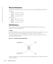
www.dell.com | support.dell.com Physical Dimensions The PowerConnect 3424/P and PowerConnect 3448/P devices have the following figure illustrates the 10/100 Base-T port LEDs on the PowerConnect 3424 /P and PowerConnect 3448/P has two LEDs marked as LNK/ACT. 40 Hardware Description The speed LED is located on the right side. The following physical dimensions: PoE ... LEDs. RJ-45 Copper Based 10/100 BaseT LEDs Speed/LNK/ACT FDX Speed/LNK/ACT FDX The RJ-45 100 Base-T port on The PowerConnect 3424 /P and PowerConnect 3448/P switches: Figure 2-6.
www.dell.com | support.dell.com Physical Dimensions The PowerConnect 3424/P and PowerConnect 3448/P devices have the following figure illustrates the 10/100 Base-T port LEDs on the PowerConnect 3424 /P and PowerConnect 3448/P has two LEDs marked as LNK/ACT. 40 Hardware Description The speed LED is located on the right side. The following physical dimensions: PoE ... LEDs. RJ-45 Copper Based 10/100 BaseT LEDs Speed/LNK/ACT FDX Speed/LNK/ACT FDX The RJ-45 100 Base-T port on The PowerConnect 3424 /P and PowerConnect 3448/P switches: Figure 2-6.
User's Guide (.htm)
Page 44
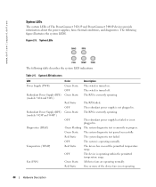
www.dell.com | support.dell.com System LEDs The system LEDs of the device fans is not operating. 44 Hardware Description The switch is not plugged in. OFF The redundant ... operating. Table 2-5. Red Static OFF Green Static The RPS failed. Green Static The system diagnostic test passed successfully. Red Static One or more of The PowerConnect 3424 /P and PowerConnect 3448/P devices provide information about the power supplies, fans, thermal conditions, and diagnostics. The RPS is currently operating. Red Static The device has crossed...
www.dell.com | support.dell.com System LEDs The system LEDs of the device fans is not operating. 44 Hardware Description The switch is not plugged in. OFF The redundant ... operating. Table 2-5. Red Static OFF Green Static The RPS failed. Green Static The system diagnostic test passed successfully. Red Static One or more of The PowerConnect 3424 /P and PowerConnect 3448/P devices provide information about the power supplies, fans, thermal conditions, and diagnostics. The RPS is currently operating. Red Static The device has crossed...
User's Guide (.htm)
Page 46
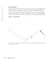
The PowerConnect 3424/P and PowerConnect 3448/P switches connect to an external EPS-470 unit to provide a redundant power option. Power Connection When the device is required. No configuration is connected ...-470 is connected. See Table 2-5 for RPS LED definition. The front panel "RPS" LED indicates whether the external RPS-600 is connected. www.dell.com | support.dell.com DC Power Supply Unit The PowerConnect 3424 and PowerConnect 3448 switches connect to an external RPS-600 unit to provide a redundant power option. No configuration is required.
The PowerConnect 3424/P and PowerConnect 3448/P switches connect to an external EPS-470 unit to provide a redundant power option. Power Connection When the device is required. No configuration is connected ...-470 is connected. See Table 2-5 for RPS LED definition. The front panel "RPS" LED indicates whether the external RPS-600 is connected. www.dell.com | support.dell.com DC Power Supply Unit The PowerConnect 3424 and PowerConnect 3448 switches connect to an external RPS-600 unit to provide a redundant power option. No configuration is required.
User's Guide (.htm)
Page 50
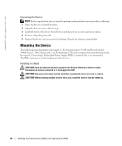
...device from the box and place it on a secure and clean surface. 4 Remove all cables from the bottom up. 50 Installing the PowerConnect 3424/P and PowerConnect 3448/P Installing in a Rack CAUTION: Read the Safety Information included in a rack or cabinet. The RPS connector is on the back ...The Console port is recommended. Mounting the Device The following mounting instructions apply to or that support the SWI. www.dell.com | support.dell.com Unpacking the Device NOTE: Before unpacking the device, inspect the package and immediately report any damage immediately. Report any...
...device from the box and place it on a secure and clean surface. 4 Remove all cables from the bottom up. 50 Installing the PowerConnect 3424/P and PowerConnect 3448/P Installing in a Rack CAUTION: Read the Safety Information included in a rack or cabinet. The RPS connector is on the back ...The Console port is recommended. Mounting the Device The following mounting instructions apply to or that support the SWI. www.dell.com | support.dell.com Unpacking the Device NOTE: Before unpacking the device, inspect the package and immediately report any damage immediately. Report any...
User's Guide (.htm)
Page 52
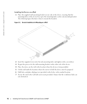
www.dell.com | support.dell.com Installing the Device on a Wall 1 Place the supplied wall-mounting bracket on one side of the device. 4 Place the device on the wall in ... the process for the wall-mounting bracket on the other side of the device, ensuring that the ventilation holes are not obstructed. 52 Installing the PowerConnect 3424/P and PowerConnect 3448/P
www.dell.com | support.dell.com Installing the Device on a Wall 1 Place the supplied wall-mounting bracket on one side of the device. 4 Place the device on the wall in ... the process for the wall-mounting bracket on the other side of the device, ensuring that the ventilation holes are not obstructed. 52 Installing the PowerConnect 3424/P and PowerConnect 3448/P
User's Guide (.htm)
Page 54
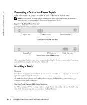
... in "Starting and Configuring the Device". NOTE: Do not connect the power cable to 192 ports are considered stacking Members. 54 Installing the PowerConnect 3424/P and PowerConnect 3448/P www.dell.com | support.dell.com Connecting a Device to a Power Supply Connect the supplied AC power cable to the AC power connector on the front panel. Back...
... in "Starting and Configuring the Device". NOTE: Do not connect the power cable to 192 ports are considered stacking Members. 54 Installing the PowerConnect 3424/P and PowerConnect 3448/P www.dell.com | support.dell.com Connecting a Device to a Power Supply Connect the supplied AC power cable to the AC power connector on the front panel. Back...
User's Guide (.htm)
Page 56
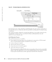
...appropriate Stack ID LED is indicated by using the Stack ID button. Unit ID 1 and 2 are for Member units. www.dell.com | support.dell.com Figure 3-6. Stacking Configuration and Identification Panel Stacking LEDs Stack ID Button Each stack device has a unique identifying unit ID ...the configured LED number (corresponding to the previously saved unit ID) begins to flash. The unit ID is illuminated. 56 Installing the PowerConnect 3424/P and PowerConnect 3448/P The default setting is connected to a VT100 terminal device or VT100 terminal emulator via the RS-232 crossover cable. 2 Locate...
...appropriate Stack ID LED is indicated by using the Stack ID button. Unit ID 1 and 2 are for Member units. www.dell.com | support.dell.com Figure 3-6. Stacking Configuration and Identification Panel Stacking LEDs Stack ID Button Each stack device has a unique identifying unit ID ...the configured LED number (corresponding to the previously saved unit ID) begins to flash. The unit ID is illuminated. 56 Installing the PowerConnect 3424/P and PowerConnect 3448/P The default setting is connected to a VT100 terminal device or VT100 terminal emulator via the RS-232 crossover cable. 2 Locate...
User's Guide (.htm)
Page 57
...button becomes unresponsive and the unit ID is set to the LED ID flashing at the end of the user documentation from the Dell Support website at a time until all external connections, connect a terminal to the device to configure the device. NOTE: These steps...female DB-9 connector for the Console port and the appropriate connector for this product. Performing the steps one unit at support.dell.com. Installing the PowerConnect 3424/P and PowerConnect 3448/P 57 Pressing the Stack ID button again advances the Stack ID to a terminal desktop system running VT100 terminal emulation ...
...button becomes unresponsive and the unit ID is set to the LED ID flashing at the end of the user documentation from the Dell Support website at a time until all external connections, connect a terminal to the device to configure the device. NOTE: These steps...female DB-9 connector for the Console port and the appropriate connector for this product. Performing the steps one unit at support.dell.com. Installing the PowerConnect 3424/P and PowerConnect 3448/P 57 Pressing the Stack ID button again advances the Stack ID to a terminal desktop system running VT100 terminal emulation ...

User's Guide (.htm)
Page 58
...dell.com | support.dell.com 3 Set the data rate to 9600 baud. 4 Set the data format to 8 data bits, 1 stop bit, and no parity. 5 Set flow control to none. 6 Under Properties, select VT100 for Emulation mode. 7 Select Terminal keys for Terminal keys (not Windows keys). Figure 3-7. Connecting to PowerConnect... in the stack, but stack management is performed only from the stack master (unit ID 1 or 2). 58 Installing the PowerConnect 3424/P and PowerConnect 3448/P NOTICE: When using HyperTerminal with Microsoft® Windows® 2000,ensure that the setting is on any unit in ...
...dell.com | support.dell.com 3 Set the data rate to 9600 baud. 4 Set the data format to 8 data bits, 1 stop bit, and no parity. 5 Set flow control to none. 6 Under Properties, select VT100 for Emulation mode. 7 Select Terminal keys for Terminal keys (not Windows keys). Figure 3-7. Connecting to PowerConnect... in the stack, but stack management is performed only from the stack master (unit ID 1 or 2). 58 Installing the PowerConnect 3424/P and PowerConnect 3448/P NOTICE: When using HyperTerminal with Microsoft® Windows® 2000,ensure that the setting is on any unit in ...
User's Guide (.htm)
Page 59
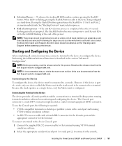
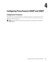
The order of installation and configuration procedures is connected to the device to monitor the boot and other procedures. Configuring PowerConnect 3424/P and 3448/P 59 Configuring PowerConnect 3424/P and 3448/P Configuration Procedures After all the device external connections are completed, a terminal is illustrated in the following figure: NOTE: Before proceeding, read the release notes for this product. Download the release notes from support.dell.com.
The order of installation and configuration procedures is connected to the device to monitor the boot and other procedures. Configuring PowerConnect 3424/P and 3448/P 59 Configuring PowerConnect 3424/P and 3448/P Configuration Procedures After all the device external connections are completed, a terminal is illustrated in the following figure: NOTE: Before proceeding, read the release notes for this product. Download the release notes from support.dell.com.
User's Guide (.htm)
Page 60
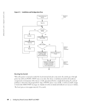
The boot process runs approximately 30 seconds. 60 Configuring PowerConnect 3424/P and 3448/P www.dell.com | support.dell.com Figure 4-1. If POST passes successfully, a valid executable image is detected, the program flow stops. POST messages are displayed on self-test (POST). Installation and ...
The boot process runs approximately 30 seconds. 60 Configuring PowerConnect 3424/P and 3448/P www.dell.com | support.dell.com Figure 4-1. If POST passes successfully, a valid executable image is detected, the program flow stops. POST messages are displayed on self-test (POST). Installation and ...
User's Guide (.htm)
Page 61
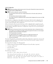
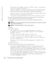
... mode. The initial device configuration is to Dell Easy Setup Wizard The Setup Wizard guides you through the initial switch configuration, and gets you through an interface defined during the initial configuration. Configuring PowerConnect 3424/P and 3448/P 61 NOTE: Obtain the... following information from the network administrator before and is in the same state as when you received it. • The PowerConnect device booted successfully. • The console...
... mode. The initial device configuration is to Dell Easy Setup Wizard The Setup Wizard guides you through the initial switch configuration, and gets you through an interface defined during the initial configuration. Configuring PowerConnect 3424/P and 3448/P 61 NOTE: Obtain the... following information from the network administrator before and is in the same state as when you received it. • The PowerConnect device booted successfully. • The console...
User's Guide (.htm)
Page 62
... the default system configuration. The following is displayed: The system is retrieved from the BootP server. www.dell.com | support.dell.com The system will continue with a default answer; For more information on adding management systems, see the...Dell Network Manager or CLI to continue the Setup Wizard. NOTE: If there is a BootP server on setting up SNMP accounts, please see the user documentation. If you enter [Y], the Setup Wizard provides interactive guidance through the initial device configuration. To add a management station: 62 Configuring PowerConnect 3424...
... the default system configuration. The following is displayed: The system is retrieved from the BootP server. www.dell.com | support.dell.com The system will continue with a default answer; For more information on adding management systems, see the...Dell Network Manager or CLI to continue the Setup Wizard. NOTE: If there is a BootP server on setting up SNMP accounts, please see the user documentation. If you enter [Y], the Setup Wizard provides interactive guidance through the initial device configuration. To add a management station: 62 Configuring PowerConnect 3424...
User's Guide (.htm)
Page 86
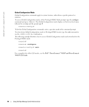
... EXEC mode: console# console# configure console(config)# exit console# For a complete list of the CLI modes, see the Dell™ PowerConnect™3424/P and PowerConnect 3448/P CLI Guide. 86 Using Dell OpenManage Switch Administrator www.dell.com | support.dell.com Global Configuration Mode Global Configuration commands apply to system features, rather than a specific protocol or interface. The...
... EXEC mode: console# console# configure console(config)# exit console# For a complete list of the CLI modes, see the Dell™ PowerConnect™3424/P and PowerConnect 3448/P CLI Guide. 86 Using Dell OpenManage Switch Administrator www.dell.com | support.dell.com Global Configuration Mode Global Configuration commands apply to system features, rather than a specific protocol or interface. The...

User's Guide Addendum (.pdf)
Page 1
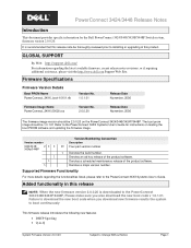
... Corporation disclaims any products or specifications referred to herein to either the entity claiming the marks and names or their products. Dell™ PowerConnect™ 3424/3448/3424P/3448P PowerConnect 3424/3448/3424P/3448P Release Notes Date: November 2006 System Firmware Version 2.0.0.20 Information in this document is strictly forbidden. All rights reserved. Trademarks used...
... Corporation disclaims any products or specifications referred to herein to either the entity claiming the marks and names or their products. Dell™ PowerConnect™ 3424/3448/3424P/3448P PowerConnect 3424/3448/3424P/3448P Release Notes Date: November 2006 System Firmware Version 2.0.0.20 Information in this document is strictly forbidden. All rights reserved. Trademarks used...
User's Guide Addendum (.pdf)
Page 4
... software. Added functionality in -Q System Firmware Version 2.0.0.20 Subject to the PowerConnect 34XX Systems User's Guide for the Dell PowerConnect 3424/3448/3424P/3448P Switch system, firmware version 2.0.0.20. PowerConnect 3424/3448 Release Notes Introduction This document provides specific information for instructions on the PowerConnect 3424/3448/3424P/3448P. Denotes a scheduled maintenance release of the product software. Supported...
... software. Added functionality in -Q System Firmware Version 2.0.0.20 Subject to the PowerConnect 34XX Systems User's Guide for the Dell PowerConnect 3424/3448/3424P/3448P Switch system, firmware version 2.0.0.20. PowerConnect 3424/3448 Release Notes Introduction This document provides specific information for instructions on the PowerConnect 3424/3448/3424P/3448P. Denotes a scheduled maintenance release of the product software. Supported...


