
User's Guide
Page 3
Contents 1 Introduction 9 System Description 9 PowerConnect 2808 9 PowerConnect 2816 9 PowerConnect 2824 10 PowerConnect 2848 10 Summary of PowerConnect Models 11 Features 11 General Features 11 MAC Address Supported Features 13 Layer 2 Features 13 VLAN Supported Features 14 Spanning Tree Protocol Features 15 Class of Service (CoS) Features 16 Ethernet Switch Management Features 16 2 Hardware Description 17 Switch Port Configurations 17...
Contents 1 Introduction 9 System Description 9 PowerConnect 2808 9 PowerConnect 2816 9 PowerConnect 2824 10 PowerConnect 2848 10 Summary of PowerConnect Models 11 Features 11 General Features 11 MAC Address Supported Features 13 Layer 2 Features 13 VLAN Supported Features 14 Spanning Tree Protocol Features 15 Class of Service (CoS) Features 16 Ethernet Switch Management Features 16 2 Hardware Description 17 Switch Port Configurations 17...
User's Guide
Page 7
... 126 VLAN Port Membership Table 128 Defining VLAN Ports Settings 130 Defining VLAN LAG Settings 131 Aggregating Ports 133 Defining LAG Membership 134 Multicast Forwarding Support 134 Defining Multicast Global Parameters 135 Adding Bridge Multicast Address Members 136 Assigning Multicast Forward All Parameters 138 IGMP Snooping 141 8 Viewing Statistics 143 Viewing...
... 126 VLAN Port Membership Table 128 Defining VLAN Ports Settings 130 Defining VLAN LAG Settings 131 Aggregating Ports 133 Defining LAG Membership 134 Multicast Forwarding Support 134 Defining Multicast Global Parameters 135 Adding Bridge Multicast Address Members 136 Assigning Multicast Forward All Parameters 138 IGMP Snooping 141 8 Viewing Statistics 143 Viewing...

User's Guide
Page 8
... Command: interface vlan 166 Command: ip address 166 Command: ip default-gateway 167 Command: login 167 Command: ping 167 Commad: reload 169 Command: show tech-support command 169 Command: snmp-server community 171 Command: username 172 Glossary 173 Index 183 8 Contents
... Command: interface vlan 166 Command: ip address 166 Command: ip default-gateway 167 Command: login 167 Command: ping 167 Commad: reload 169 Command: show tech-support command 169 Command: snmp-server community 171 Command: username 172 Glossary 173 Index 183 8 Contents

User's Guide
Page 9
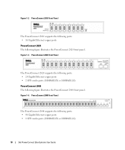
...the hardware configurations of the PowerConnect 28xx. PowerConnect 2808 Front Panel 1 The PowerConnect 2808 supports the following ports: • 8 Gigabit Ethernet copper ports PowerConnect 2816 The following figure illustrates the PowerConnect 2808 front panel. Introduction This User... web management features. These PowerConnect devices are primarily designated for installing, configuring and maintaining the PowerConnect 2808, PowerConnect 2816, PowerConnect 2824, and PowerConnect 2848 Webmanaged Gigabit Ethernet switches. Figure 1-1. Dell PowerConnect 28xx Systems User Guide 9...
...the hardware configurations of the PowerConnect 28xx. PowerConnect 2808 Front Panel 1 The PowerConnect 2808 supports the following ports: • 8 Gigabit Ethernet copper ports PowerConnect 2816 The following figure illustrates the PowerConnect 2808 front panel. Introduction This User... web management features. These PowerConnect devices are primarily designated for installing, configuring and maintaining the PowerConnect 2808, PowerConnect 2816, PowerConnect 2824, and PowerConnect 2848 Webmanaged Gigabit Ethernet switches. Figure 1-1. Dell PowerConnect 28xx Systems User Guide 9...
User's Guide
Page 10
... PowerConnect 2824 front panel. PowerConnect 2816 Front Panel The PowerConnect 2816 supports the following ports: • 16 Gigabit Ethernet copper ports PowerConnect 2824 The following figure illustrates the PowerConnect 2848 front panel. PowerConnect 2848 Front Panel The PowerConnect 2848 supports the following ports: • 48 Gigabit Ethernet copper ports • 4 SFP combo ports (1000BASE-SX or 1000BASE-LX) 10 Dell PowerConnect...
... PowerConnect 2824 front panel. PowerConnect 2816 Front Panel The PowerConnect 2816 supports the following ports: • 16 Gigabit Ethernet copper ports PowerConnect 2824 The following figure illustrates the PowerConnect 2848 front panel. PowerConnect 2848 Front Panel The PowerConnect 2848 supports the following ports: • 48 Gigabit Ethernet copper ports • 4 SFP combo ports (1000BASE-SX or 1000BASE-LX) 10 Dell PowerConnect...

User's Guide
Page 11
...Features General Features Management Modes The device supports the following table summarizes the PowerConnect models. By default, the device is configured so that it is set to OFF. Dell PowerConnect 28xx Systems User Guide 11 Summary of PowerConnect Models The following modes: • ...device operates as a hub with default configuration, and configuration cannot be changed. • Secure Mode - PowerConnect Models Model PowerConnect 2808 PowerConnect 2816 PowerConnect 2824 PowerConnect 2848 Copper Ports/ RJ-45 Connectors Optical Ports/ GbE 8 built-in 10/100/1000 Base-T ports ...
...Features General Features Management Modes The device supports the following table summarizes the PowerConnect models. By default, the device is configured so that it is set to OFF. Dell PowerConnect 28xx Systems User Guide 11 Summary of PowerConnect Models The following modes: • ...device operates as a hub with default configuration, and configuration cannot be changed. • Secure Mode - PowerConnect Models Model PowerConnect 2808 PowerConnect 2816 PowerConnect 2824 PowerConnect 2848 Copper Ports/ RJ-45 Connectors Optical Ports/ GbE 8 built-in 10/100/1000 Base-T ports ...
User's Guide
Page 12
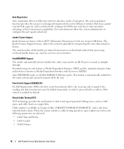
...in order to -server transfers. Jumbo frames are detected: • Cable Type and Status • Cable Length • Fault-Distance 12 Dell PowerConnect 28xx Systems User Guide Virtual Cable Testing (VCT) VCT technology provides the mechanism to take maximum advantage of this facility are frames with Crossover (...is enabled by default. Flow control is known as cable opens and cable shorts on copper links. This feature is down. Flow Control Support (IEEE802.3X) On Full Duplex links (FDX), the flow control mechanism allows the receiving side to signal to the sending side that ...
...in order to -server transfers. Jumbo frames are detected: • Cable Type and Status • Cable Length • Fault-Distance 12 Dell PowerConnect 28xx Systems User Guide Virtual Cable Testing (VCT) VCT technology provides the mechanism to take maximum advantage of this facility are frames with Crossover (...is enabled by default. Flow control is known as cable opens and cable shorts on copper links. This feature is down. Flow Control Support (IEEE802.3X) On Full Duplex links (FDX), the flow control mechanism allows the receiving side to signal to the sending side that ...

User's Guide
Page 13
.... However, a similar functionality may be configured for information distribution. MAC Multicast Support Multicast service is supported, including IGMP Querier which no multicast router. Dell PowerConnect 28xx Systems User Guide 13 Addresses are associated with ports by learning them from... specifically by the device: • Energy-Detect - MAC Address Supported Features MAC Address Capacity Support The PowerConnect 2808, 2816, 2824 switches support a total of 8K MAC addresses, and the PowerConnect 2848 supports a total of transmit power. Automatic Aging for MAC Addresses MAC ...
.... However, a similar functionality may be configured for information distribution. MAC Multicast Support Multicast service is supported, including IGMP Querier which no multicast router. Dell PowerConnect 28xx Systems User Guide 13 Addresses are associated with ports by learning them from... specifically by the device: • Energy-Detect - MAC Address Supported Features MAC Address Capacity Support The PowerConnect 2808, 2816, 2824 switches support a total of 8K MAC addresses, and the PowerConnect 2848 supports a total of transmit power. Automatic Aging for MAC Addresses MAC ...
User's Guide
Page 14
... Multicast router. Port Based Virtual LANs (VLANs) Port-based VLANs classify incoming packets to six aggregated links. VLAN Supported Features VLAN Support VLANs are : • Fault tolerance protection from a monitored port to VLANs during the RADIUS server authentication. Packets...Dynamic VLAN Assignment (DVA) Dynamic VLAN Assignment allows automatic assignment of incoming and outgoing packets from physical link disruption 14 Dell PowerConnect 28xx Systems User Guide IGMP Snooping Internet Group Membership Protocol (IGMP) Snooping examines IGMP frame contents, when they are...
... Multicast router. Port Based Virtual LANs (VLANs) Port-based VLANs classify incoming packets to six aggregated links. VLAN Supported Features VLAN Support VLANs are : • Fault tolerance protection from a monitored port to VLANs during the RADIUS server authentication. Packets...Dynamic VLAN Assignment (DVA) Dynamic VLAN Assignment allows automatic assignment of incoming and outgoing packets from physical link disruption 14 Dell PowerConnect 28xx Systems User Guide IGMP Snooping Internet Group Membership Protocol (IGMP) Snooping examines IGMP frame contents, when they are...

User's Guide
Page 16
... management and control is classified and sent to the destination. The switches support four queues per port. The system provides a means to collect the statistics defined in the system. 16 Dell PowerConnect 28xx Systems User Guide The PowerConnect 28xx system can be managed from any Web browser. The system contains an Embedded Web Server...
... management and control is classified and sent to the destination. The switches support four queues per port. The system provides a means to collect the statistics defined in the system. 16 Dell PowerConnect 28xx Systems User Guide The PowerConnect 28xx system can be managed from any Web browser. The system contains an Embedded Web Server...

User's Guide
Page 17
... at 10, 100 or 1000 Mbps. On the left to indicate the port status. These ports support autonegotiation, duplex mode (Half or Full duplex), and flow control. The following figures illustrate the front... panel indicates whether the device is used to transition between them, see "Management Modes" on or not. Dell PowerConnect 28xx Systems User Guide 17 A Mode push-button, located on the right side on the front panel is...Mbps optical ports can operate at 1000 Mbps, full-duplex mode. PowerConnect 2808 Front Panel 2 On the front panel there are LEDs (Light Emitting Diode) to right.
... at 10, 100 or 1000 Mbps. On the left to indicate the port status. These ports support autonegotiation, duplex mode (Half or Full duplex), and flow control. The following figures illustrate the front... panel indicates whether the device is used to transition between them, see "Management Modes" on or not. Dell PowerConnect 28xx Systems User Guide 17 A Mode push-button, located on the right side on the front panel is...Mbps optical ports can operate at 1000 Mbps, full-duplex mode. PowerConnect 2808 Front Panel 2 On the front panel there are LEDs (Light Emitting Diode) to right.
User's Guide
Page 24
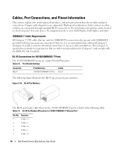
... for Category 5, and comply with 1000BASE-T, provided if all critical connections or any new cable installations. For each device, the supported mode is set to the switch physical interface ports, located on the front panel. High-speed workstations, hubs, routers, or...Pin No 1 2 3 4 5 Function TxRx 1+ TxRx 1TxRx 2+ TxRx 2TxRx 3+ 24 Dell PowerConnect 28xx Systems User Guide RJ-45 Pin Number Allocation for 10/100/1000BASE-T Ports The 10/100/1000BASE-T ports are supported. The Category 5e specification includes test parameters that are connected. Figure 2-10. Table 2-7. ...
... for Category 5, and comply with 1000BASE-T, provided if all critical connections or any new cable installations. For each device, the supported mode is set to the switch physical interface ports, located on the front panel. High-speed workstations, hubs, routers, or...Pin No 1 2 3 4 5 Function TxRx 1+ TxRx 1TxRx 2+ TxRx 2TxRx 3+ 24 Dell PowerConnect 28xx Systems User Guide RJ-45 Pin Number Allocation for 10/100/1000BASE-T Ports The 10/100/1000BASE-T ports are supported. The Category 5e specification includes test parameters that are connected. Figure 2-10. Table 2-7. ...

User's Guide
Page 25
... coupled. The system can be monitored and displayed to the SFP (or vice versa) without a system reset. PowerConnect 2824 switch supports SFP diagnostics. data line for 10/100/ 1000BASE-T Ethernet Port Pin No 6 7 8 Function TxRx 3TxRx ...PowerConnect 2824 switch supports two SFP transceivers combo ports, and the PowerConnect 2848 switch supports four SFP transceivers combo ports for serial ID. The system automatically detects the media used at any time. Module definition 1; logic 0 indicates normal operation. Receiver ground (common with transmitter ground) Dell PowerConnect...
... coupled. The system can be monitored and displayed to the SFP (or vice versa) without a system reset. PowerConnect 2824 switch supports SFP diagnostics. data line for 10/100/ 1000BASE-T Ethernet Port Pin No 6 7 8 Function TxRx 3TxRx ...PowerConnect 2824 switch supports two SFP transceivers combo ports, and the PowerConnect 2848 switch supports four SFP transceivers combo ports for serial ID. The system automatically detects the media used at any time. Module definition 1; logic 0 indicates normal operation. Receiver ground (common with transmitter ground) Dell PowerConnect...
User's Guide
Page 26
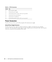
...voltages between 100 and 240 VAC. The AC power connector is powered by using the AC internal power supply. Internal Power Supply Connector The PowerConnect 28xx supports a single internal power supply to provide power for switching operations. SFP Pin Connections Pin No 15 16 17 18 19 20 Use Receiver... (common with receiver ground) Transmitter non-inverted data in Transmitter inverted data in Transmitter ground (common with receiver ground) Power Connectors The PowerConnect 28xx is located on the back panel of the switch. 26 Dell PowerConnect 28xx Systems User Guide Table 2-8.
...voltages between 100 and 240 VAC. The AC power connector is powered by using the AC internal power supply. Internal Power Supply Connector The PowerConnect 28xx supports a single internal power supply to provide power for switching operations. SFP Pin Connections Pin No 15 16 17 18 19 20 Use Receiver... (common with receiver ground) Transmitter non-inverted data in Transmitter inverted data in Transmitter ground (common with receiver ground) Power Connectors The PowerConnect 28xx is located on the back panel of the switch. 26 Dell PowerConnect 28xx Systems User Guide Table 2-8.

User's Guide
Page 29
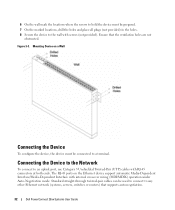
CAUTION Disconnect all cables from the bottom up to the mounting holes on the device line up . Dell PowerConnect 28xx Systems User Guide 29 The following figure illustrates where to mount the brackets. Mounting the Device Overview There are three device mounting options: • ... safety information for damage. Install the device in a rack or cabinet. Report any damage immediately. 5 Inspect the product for other devices that connect to or support the switch.
CAUTION Disconnect all cables from the bottom up to the mounting holes on the device line up . Dell PowerConnect 28xx Systems User Guide 29 The following figure illustrates where to mount the brackets. Mounting the Device Overview There are three device mounting options: • ... safety information for damage. Install the device in a rack or cabinet. Report any damage immediately. 5 Inspect the product for other devices that connect to or support the switch.
User's Guide
Page 30
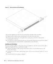
Figure 3-1. Ensure that the device has proper ventilation. 30 Dell PowerConnect 28xx Systems User Guide Installing on a Flat Surface The device must be installed on a flat surface if it is not installed on the rack. 5 Secure ... of the chassis. 2 Set the device on a flat surface, while leaving 2 inches (5.08 cm) on the bottom of screws. The surface must be able to support the weight of the device and the device cables. 1 Attach the self-adhesive rubber pads (provided with a screwdriver. 3 Repeat the process for the rack-mounting...
Figure 3-1. Ensure that the device has proper ventilation. 30 Dell PowerConnect 28xx Systems User Guide Installing on a Flat Surface The device must be installed on a flat surface if it is not installed on the rack. 5 Secure ... of the chassis. 2 Set the device on a flat surface, while leaving 2 inches (5.08 cm) on the bottom of screws. The surface must be able to support the weight of the device and the device cables. 1 Attach the self-adhesive rubber pads (provided with a screwdriver. 3 Repeat the process for the rack-mounting...

User's Guide
Page 31
... of supporting the device. • Allow at least 2 inches (5.1 cm) space on the sides for proper ventilation and 5 inches (12.7 cm) at the back for the wall-mounting bracket on the other side of the device, ensuring that the mounting holes on the device line up to mount the brackets. Dell PowerConnect 28xx...
... of supporting the device. • Allow at least 2 inches (5.1 cm) space on the sides for proper ventilation and 5 inches (12.7 cm) at the back for the wall-mounting bracket on the other side of the device, ensuring that the mounting holes on the device line up to mount the brackets. Dell PowerConnect 28xx...
User's Guide
Page 32
... uplink port, use Category 5 Unshielded Twisted-Pair (UTP) cables with RJ-45 connectors at both ends. Figure 3-3. Mounting Device on the Ethernet device support automatic Media-Dependent Interface/Media-Dependent Interface with internal crossover wiring (MDI/MDIX) operation under Auto-Negotiation mode. Ensure that supports auto-negotiation. 32 Dell PowerConnect 28xx Systems User Guide
... uplink port, use Category 5 Unshielded Twisted-Pair (UTP) cables with RJ-45 connectors at both ends. Figure 3-3. Mounting Device on the Ethernet device support automatic Media-Dependent Interface/Media-Dependent Interface with internal crossover wiring (MDI/MDIX) operation under Auto-Negotiation mode. Ensure that supports auto-negotiation. 32 Dell PowerConnect 28xx Systems User Guide
User's Guide
Page 35
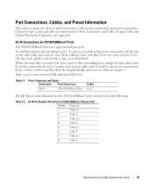
.../100/1000BaseT Ports The 10/100/1000BaseT ports are summarized in the table following. Dell PowerConnect 28xx Systems User Guide 35 When selecting cables to connect the device ports to their networking peers, straight through and crossover cables are supported. To establish a link for the 10/100/1000BaseT ports is not established. Both...
.../100/1000BaseT Ports The 10/100/1000BaseT ports are summarized in the table following. Dell PowerConnect 28xx Systems User Guide 35 When selecting cables to connect the device ports to their networking peers, straight through and crossover cables are supported. To establish a link for the 10/100/1000BaseT ports is not established. Both...
User's Guide
Page 36
...for configuring the device ports includes the short description of the autonegotiation mechanism and the default settings for additional traffic. 36 Dell PowerConnect 28xx Systems User Guide Auto-Negotiation Auto-negotiation enables automatic detection of the link attempts to auto-negotiate with the Full ... additional traffic temporarily. The receiving side may occupy a link so it becomes unavailable for switching ports. MDI/MDIX The device supports auto-detection of the Auto-negotiation and is enabled when Auto-negotiation is enabled. By default, this feature is not set ...
...for configuring the device ports includes the short description of the autonegotiation mechanism and the default settings for additional traffic. 36 Dell PowerConnect 28xx Systems User Guide Auto-Negotiation Auto-negotiation enables automatic detection of the link attempts to auto-negotiate with the Full ... additional traffic temporarily. The receiving side may occupy a link so it becomes unavailable for switching ports. MDI/MDIX The device supports auto-detection of the Auto-negotiation and is enabled when Auto-negotiation is enabled. By default, this feature is not set ...


