
Information Update
Page 1
... advisable to change the IP address of this mode, you want to Web-managed mode and the Managed Mode LED will be illuminated green. NOTE: The Managed Mode button is recessed to the factory default settings. NOTE: To access the device through the Web interface, see "Initial Configuration" in Dell PowerConnect 27xx Systems User's Guide. The switch changes to...
... advisable to change the IP address of this mode, you want to Web-managed mode and the Managed Mode LED will be illuminated green. NOTE: The Managed Mode button is recessed to the factory default settings. NOTE: To access the device through the Web interface, see "Initial Configuration" in Dell PowerConnect 27xx Systems User's Guide. The switch changes to...
Information Update
Page 2
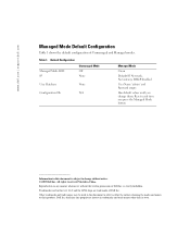
...subject to either the entities claiming the marks and names or their products. Dell Inc. Table 1. Default Configuration Managed Mode LED IP Unmanaged Mode Off None User Database None Configuration Db N/A Managed Mode Green Default IP, Net mask, No Gateway, DHCP disabled User Name '...admin' and Password empty Has default values until you press the Managed Mode button Information in this text: Dell and the DELL logo are trademarks of Unmanaged and Managed modes. Trademarks used in this document is strictly forbidden. disclaims any manner whatsoever without ...
...subject to either the entities claiming the marks and names or their products. Dell Inc. Table 1. Default Configuration Managed Mode LED IP Unmanaged Mode Off None User Database None Configuration Db N/A Managed Mode Green Default IP, Net mask, No Gateway, DHCP disabled User Name '...admin' and Password empty Has default values until you press the Managed Mode button Information in this text: Dell and the DELL logo are trademarks of Unmanaged and Managed modes. Trademarks used in this document is strictly forbidden. disclaims any manner whatsoever without ...

User's Guide
Page 3
... 13 Port Default Settings 13 2 Hardware Description Switch Port Configurations 15 PowerConnect 2708/2716/2724/2748 Front Panel Port Description . . . . 15 Physical Dimensions 19 LED Definitions 19 Power LED 19 Managed Mode LED 19 Fan LED (2748 only 20 Port LEDs 20 Managed Mode Button 21 Switch Ventilation Fan 22 Cables, Port Connections, and Pinout Information 22...
... 13 Port Default Settings 13 2 Hardware Description Switch Port Configurations 15 PowerConnect 2708/2716/2724/2748 Front Panel Port Description . . . . 15 Physical Dimensions 19 LED Definitions 19 Power LED 19 Managed Mode LED 19 Fan LED (2748 only 20 Port LEDs 20 Managed Mode Button 21 Switch Ventilation Fan 22 Cables, Port Connections, and Pinout Information 22...

User's Guide
Page 9
... in traffic delays and frame loss caused by the user configuring the switch in Managed Mode, configures the switch as desired, and then switches to OFF. From Unmanaged Mode, when the Managed Mode button is pressed, the switch enters Unmanaged Mode. • Secure Mode (PowerConnect 2748 only) - HOL blocking queues packets, and the packets at the head of the...
... in traffic delays and frame loss caused by the user configuring the switch in Managed Mode, configures the switch as desired, and then switches to OFF. From Unmanaged Mode, when the Managed Mode button is pressed, the switch enters Unmanaged Mode. • Secure Mode (PowerConnect 2748 only) - HOL blocking queues packets, and the packets at the head of the...

User's Guide
Page 11
..., 2716, and 2724 switches support a total of 8K MAC addresses, and the PowerConnect 2748 supports a total of incoming and outgoing packets from a monitored port to a monitoring port. The MAC addresses are associated with ports by learning them from...are forwarded based only on the relevant VLAN. When Layer 2 frames are forwarded, Broadcast and Multicast frames are aged out. Managed and Secure Modes VLAN-aware MAC-based Switching In Managed or Secure mode, the switch system always performs VLAN-aware bridging. However, a similar functionality may be configured for a given period of all...
..., 2716, and 2724 switches support a total of 8K MAC addresses, and the PowerConnect 2748 supports a total of incoming and outgoing packets from a monitored port to a monitoring port. The MAC addresses are associated with ports by learning them from...are forwarded based only on the relevant VLAN. When Layer 2 frames are forwarded, Broadcast and Multicast frames are aged out. Managed and Secure Modes VLAN-aware MAC-based Switching In Managed or Secure mode, the switch system always performs VLAN-aware bridging. However, a similar functionality may be configured for a given period of all...

User's Guide
Page 15
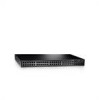
...the device is the Managed Mode LED which indicates the Ethernet switch operational status. These ports support autonegotiation, duplex mode (Half or Full duplex), and flow control. On the left to 8, top down and left side of the PowerConnect 2708/2716/2724/2748 switches. The following...only operate at 10, 100 or 1000 Mbps. 2 Hardware Description Switch Port Configurations PowerConnect 2708/2716/2724/2748 Front Panel Port Description The Dell™ PowerConnect™ 2708, 2716, 2724 and 2748 switches use 10/100/1000BASE-T ports on the front panel for connecting to indicate the...
...the device is the Managed Mode LED which indicates the Ethernet switch operational status. These ports support autonegotiation, duplex mode (Half or Full duplex), and flow control. On the left to 8, top down and left side of the PowerConnect 2708/2716/2724/2748 switches. The following...only operate at 10, 100 or 1000 Mbps. 2 Hardware Description Switch Port Configurations PowerConnect 2708/2716/2724/2748 Front Panel Port Description The Dell™ PowerConnect™ 2708, 2716, 2724 and 2748 switches use 10/100/1000BASE-T ports on the front panel for connecting to indicate the...

User's Guide
Page 16
... front panel is powered on the front panel, restores the device's default settings configuration. PowerConnect 2716 Back Panel 16 Figure 2-4. On the left to indicate the port status. PowerConnect 2708 Back Panel Figure 2-3. The Power LED on the front panel indicates whether the device is the Managed Mode LED which are LEDs to right.
... front panel is powered on the front panel, restores the device's default settings configuration. PowerConnect 2716 Back Panel 16 Figure 2-4. On the left to indicate the port status. PowerConnect 2708 Back Panel Figure 2-3. The Power LED on the front panel indicates whether the device is the Managed Mode LED which are LEDs to right.

User's Guide
Page 17
...there are 24 ports which are LEDs to indicate the port status. NOTE: Only one time. The system automatically detects the media used . Figure 2-6. PowerConnect 2724 Back Panel 17 On each port there are numbered 1 to 24, top down and left side of a combo port can switch from the RJ... the left to the SFP (or vice versa) without resetting the device. The Power LED on or not. NOTE: The system can be disabled. A Managed Mode push-button, located on the far right side on a combo port, and utilizes the information in all the control interfaces. There are logical ports with...
...there are 24 ports which are LEDs to indicate the port status. NOTE: Only one time. The system automatically detects the media used . Figure 2-6. PowerConnect 2724 Back Panel 17 On each port there are numbered 1 to 24, top down and left side of a combo port can switch from the RJ... the left to the SFP (or vice versa) without resetting the device. The Power LED on or not. NOTE: The system can be disabled. A Managed Mode push-button, located on the far right side on a combo port, and utilizes the information in all the control interfaces. There are logical ports with...

User's Guide
Page 18
...on or not. The system automatically detects the media used at any one time. PowerConnect 2748 Back Panel 18 NOTE: Only one of the two physical connections of the PowerConnect 2748 device. A Managed Mode push-button, located on the far right side on the front panel, sets ...the device management mode. Figure 2-8. There are logical ports with two physical connections: • An RJ-45 connection for ...
...on or not. The system automatically detects the media used at any one time. PowerConnect 2748 Back Panel 18 NOTE: Only one of the two physical connections of the PowerConnect 2748 device. A Managed Mode push-button, located on the far right side on the front panel, sets ...the device management mode. Figure 2-8. There are logical ports with two physical connections: • An RJ-45 connection for ...
User's Guide
Page 19
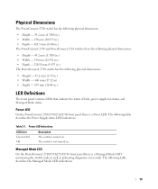
... Definitions The front panel contains LEDs that indicate the status of links, power supply, fan status, and Managed Mode status. Managed Mode LED On the PowerConnect 2708/2716/2724/2748 front panel there is not turned on . Physical Dimensions The PowerConnect 2708 switch has the following physical dimensions: • Height - 43.2 mm (1.7008 in.) • Width - 256...
... Definitions The front panel contains LEDs that indicate the status of links, power supply, fan status, and Managed Mode status. Managed Mode LED On the PowerConnect 2708/2716/2724/2748 front panel there is not turned on . Physical Dimensions The PowerConnect 2708 switch has the following physical dimensions: • Height - 43.2 mm (1.7008 in.) • Width - 256...
User's Guide
Page 20
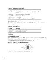
...-based 10/100/1000BASE-T LEDs The RJ-45 LED indications are operating correctly. Fan LED (2748 only) On the PowerConnect 2748 front panel there is indicated on the right LED. Table 2-2. Indicates the switch is in progress, firmware loading, or Managed Mode transition. Speed/Link/Activity is indicated on the left LED and the duplex...
...-based 10/100/1000BASE-T LEDs The RJ-45 LED indications are operating correctly. Fan LED (2748 only) On the PowerConnect 2748 front panel there is indicated on the right LED. Table 2-2. Indicates the switch is in progress, firmware loading, or Managed Mode transition. Speed/Link/Activity is indicated on the left LED and the duplex...

User's Guide
Page 21
... Green Flashing Activity is for changing between Managed Mode and Unmanaged (or Secure) Mode. Managed Mode Button The PowerConnect 2708/2716/2724/2748 has a Managed Mode push button on the front panel. After a change from Unmanaged (or Secure) Mode to Managed Mode, the switch restores the configuration values to ... or 100 Mbps. The port is transmitting or receiving data at 1000 Mbps. The Managed Mode button is occurring. From Unmanaged or Secure Mode (2748 only), pressing the Managed Mode button causes: • Factory default configuration (192.168.2.1) is set as the switch...
... Green Flashing Activity is for changing between Managed Mode and Unmanaged (or Secure) Mode. Managed Mode Button The PowerConnect 2708/2716/2724/2748 has a Managed Mode push button on the front panel. After a change from Unmanaged (or Secure) Mode to Managed Mode, the switch restores the configuration values to ... or 100 Mbps. The port is transmitting or receiving data at 1000 Mbps. The Managed Mode button is occurring. From Unmanaged or Secure Mode (2748 only), pressing the Managed Mode button causes: • Factory default configuration (192.168.2.1) is set as the switch...
User's Guide
Page 25
... push foreign objects into the device's hardware enclosure, as a managed switch, they can simply plug the switch in Unmanaged Mode. No configuration is delivered from the factory in and start using...switch is necessary. If the user wishes to change the switch 25 3 Installing the Dell™ PowerConnect™ 27XX This chapter contains information about unpacking, installation procedures, and how to water... the switch as explained in the Product Information Guide. Overview The PowerConnect 2708/2716/2724/2748 are to be serviced by trained service technicians only. • Ensure...
... push foreign objects into the device's hardware enclosure, as a managed switch, they can simply plug the switch in Unmanaged Mode. No configuration is delivered from the factory in and start using...switch is necessary. If the user wishes to change the switch 25 3 Installing the Dell™ PowerConnect™ 27XX This chapter contains information about unpacking, installation procedures, and how to water... the switch as explained in the Product Information Guide. Overview The PowerConnect 2708/2716/2724/2748 are to be serviced by trained service technicians only. • Ensure...
User's Guide
Page 26
Site Requirements The PowerConnect 2708/2716/2724/2748 devices can be mounted in a standard equipment rack, placed on a tabletop, or mounted on a power supply or any part that has the following site requirements: • Power - Cabling is routed to Dell. Safety CAUTION: Never remove the ... Figure 3-1. to Managed Mode. If the device has two power supplies, the site should have two power outlets with one of up to 113F) at a relative humidity of these components. The chapter "Starting and Configuring the Dell™PowerConnect™ 2708/2716/2724/2748 for operator access...
Site Requirements The PowerConnect 2708/2716/2724/2748 devices can be mounted in a standard equipment rack, placed on a tabletop, or mounted on a power supply or any part that has the following site requirements: • Power - Cabling is routed to Dell. Safety CAUTION: Never remove the ... Figure 3-1. to Managed Mode. If the device has two power supplies, the site should have two power outlets with one of up to 113F) at a relative humidity of these components. The chapter "Starting and Configuring the Dell™PowerConnect™ 2708/2716/2724/2748 for operator access...

User's Guide
Page 33
...process fails and the Managed Mode LED indicator turns solid amber (PowerConnect 2748). The Managed Mode LED indicates whether POST has passed successfully or failed. When a critical problem is detected, the program flow stops. This section describes how to manage the device, you...Managed Mode LED indicator is delivered from the Dell Support Website at support.dell.com. Initial Configuration The switch is off if in Unmanaged Mode, and solid green if in Unmanaged Mode. No configuration is obtained from the factory in Managed Mode. 4 Starting and Configuring the Dell™ PowerConnect...
...process fails and the Managed Mode LED indicator turns solid amber (PowerConnect 2748). The Managed Mode LED indicates whether POST has passed successfully or failed. When a critical problem is detected, the program flow stops. This section describes how to manage the device, you...Managed Mode LED indicator is delivered from the Dell Support Website at support.dell.com. Initial Configuration The switch is off if in Unmanaged Mode, and solid green if in Unmanaged Mode. No configuration is obtained from the factory in Managed Mode. 4 Starting and Configuring the Dell™ PowerConnect...
User's Guide
Page 34
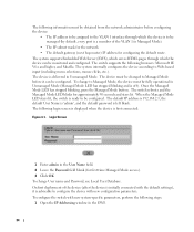
...default User Name is 'admin', and the default password is ready to be configured. Login Screen 1 Enter admin in Unmanaged Mode (Managed Mode LED has stopped blinking and is first connected: Figure 4-1. The following information must be obtained from the network administrator before it ... with new system-specific parameters, perform the following steps: 1 Open the IP Addressing window in Unmanaged Mode. Once the Managed Mode LED has stopped blinking, press the Managed Mode button. To configure the switch with new configuration parameters. To change User name and Password, see Local...
...default User Name is 'admin', and the default password is ready to be configured. Login Screen 1 Enter admin in Unmanaged Mode (Managed Mode LED has stopped blinking and is first connected: Figure 4-1. The following information must be obtained from the network administrator before it ... with new system-specific parameters, perform the following steps: 1 Open the IP Addressing window in Unmanaged Mode. Once the Managed Mode LED has stopped blinking, press the Managed Mode button. To configure the switch with new configuration parameters. To change User name and Password, see Local...
User's Guide
Page 40
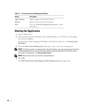
... Switch IP address (the default IP address is configured with a default IP address, user login and password. PowerConnect Switch Management Buttons Button Apply Changes Refresh Print Description Applies changes to the Ethernet Switch, see "Managed Mode Button". The Dell PowerConnect OpenManage Switch Administrator home page opens. 40 NOTE: Passwords are both case-sensitive and alphanumeric. 4 Click...
... Switch IP address (the default IP address is configured with a default IP address, user login and password. PowerConnect Switch Management Buttons Button Apply Changes Refresh Print Description Applies changes to the Ethernet Switch, see "Managed Mode Button". The Dell PowerConnect OpenManage Switch Administrator home page opens. 40 NOTE: Passwords are both case-sensitive and alphanumeric. 4 Click...
User's Guide
Page 44
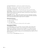
...Address, Subnet Mask and the device's static Default Gateway Address. When the Dynamic Host Configuration Protocol (DHCP) client is configured according to manage the device. When the DHCP Address is applied, the switch is enabled, the switch requests from the DHCP server to assign a dynamic...clicked, the current configuration will be saved and the device will become Secure and will no longer be able to manually set dynamically. Secure Mode (2748 only) - Specifies the user-defined switch reference. Service Tag - For example, 41 days, 2 hours, 22 minutes, and 15 seconds....
...Address, Subnet Mask and the device's static Default Gateway Address. When the Dynamic Host Configuration Protocol (DHCP) client is configured according to manage the device. When the DHCP Address is applied, the switch is enabled, the switch requests from the DHCP server to assign a dynamic...clicked, the current configuration will be saved and the device will become Secure and will no longer be able to manually set dynamically. Secure Mode (2748 only) - Specifies the user-defined switch reference. Service Tag - For example, 41 days, 2 hours, 22 minutes, and 15 seconds....
User's Guide
Page 81
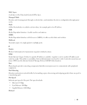
... from one port to a monitoring port. Port speeds include: • Ethernet 10 Mbps • Fast Ethernet 100Mbps • Gigabit Ethernet 1000 Mbps Protocol 81 Managed Mode Provides switch management through a web interface, and maintains the device configuration through power cycles. This utility is essentially a System Administrator's tool used for end stations. A cable used...
... from one port to a monitoring port. Port speeds include: • Ethernet 10 Mbps • Fast Ethernet 100Mbps • Gigabit Ethernet 1000 Mbps Protocol 81 Managed Mode Provides switch management through a web interface, and maintains the device configuration through power cycles. This utility is essentially a System Administrator's tool used for end stations. A cable used...
User's Guide - Addendum
Page 2
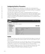
...into a single brodcast domain, regardless of VLANs in both directions, while the Current Duplex Mode is 10 Mbps as maximum speed and interface media type. VLANs managed through the port. Interface Configuration VLANs VLANs are logical subgroups within subgroups. In the following... figure illustrates the concept of the physical LAN segment to which they are implemented. www.dell.com | support.dell.com Configuring Interface Parameters...
...into a single brodcast domain, regardless of VLANs in both directions, while the Current Duplex Mode is 10 Mbps as maximum speed and interface media type. VLANs managed through the port. Interface Configuration VLANs VLANs are logical subgroups within subgroups. In the following... figure illustrates the concept of the physical LAN segment to which they are implemented. www.dell.com | support.dell.com Configuring Interface Parameters...


