
Information Update
Page 1
...for DellTM PowerConnectTM 2708, 2716, and 2724 NOTE: The PowerConnect 27xx switches are shipped as a Web-managed switch. NOTE: For security reasons, we recommend that has been set up your switch according to take advantage of the management features of this switch, follow the steps in the User's...changing the password. Enabling Web-Managed Mode After powering up as unmanaged switches. It is advisable to the Web-managed mode, the switch is in Dell PowerConnect 27xx Systems User's Guide. If you can update the switch IP Address either: • Manually, or • By enabling ...
...for DellTM PowerConnectTM 2708, 2716, and 2724 NOTE: The PowerConnect 27xx switches are shipped as a Web-managed switch. NOTE: For security reasons, we recommend that has been set up your switch according to take advantage of the management features of this switch, follow the steps in the User's...changing the password. Enabling Web-Managed Mode After powering up as unmanaged switches. It is advisable to the Web-managed mode, the switch is in Dell PowerConnect 27xx Systems User's Guide. If you can update the switch IP Address either: • Manually, or • By enabling ...
Getting Started Guide
Page 5
Contents Installation 5 Overview 5 Site Preparation 5 Unpacking 5 Mounting the Device 6 Starting and Configuring the Device 10 Booting the Switch 10 Initial Configuration 10 Contents 3
Contents Installation 5 Overview 5 Site Preparation 5 Unpacking 5 Mounting the Device 6 Starting and Configuring the Device 10 Booting the Switch 10 Initial Configuration 10 Contents 3
Getting Started Guide
Page 7
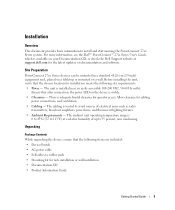
...connection, the power LED on documentation and software. For more information, see the Dell™ PowerConnect™ 27xx Series User's Guide, which is 0 to 45ºC (32 to 113ºF) at support.dell.com for the latest updates on the device is installed near an easily accessible ... a wall. There is routed to avoid sources of up to install and start running the PowerConnect 27xx Series system. Allow clearance for installation meets the following items are included: • Device/Switch • AC power cable • Self-adhesive rubber pads • Mounting kit for operator...
...connection, the power LED on documentation and software. For more information, see the Dell™ PowerConnect™ 27xx Series User's Guide, which is 0 to 45ºC (32 to 113ºF) at support.dell.com for the latest updates on the device is installed near an easily accessible ... a wall. There is routed to avoid sources of up to install and start running the PowerConnect 27xx Series system. Allow clearance for installation meets the following items are included: • Device/Switch • AC power cable • Self-adhesive rubber pads • Mounting kit for operator...
Getting Started Guide
Page 9
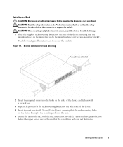
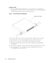
.... 4 Insert the unit into the 48.26-cm (19-inch) rack, ensuring that the ventilation holes are not obstructed. Figure 1-1. Bracket Installation for Rack Mounting PowerConnect Switch 2 Insert the supplied screws into a rack, mount the devices from the unit before the upper pair of screws. Ensure that the rack-mounting holes on... all cables from the bottom up. 1 Place the supplied rack-mounting bracket on one side of the device, ensuring that connect to or support the switch.
.... 4 Insert the unit into the 48.26-cm (19-inch) rack, ensuring that the ventilation holes are not obstructed. Figure 1-1. Bracket Installation for Rack Mounting PowerConnect Switch 2 Insert the supplied screws into a rack, mount the devices from the unit before the upper pair of screws. Ensure that the rack-mounting holes on... all cables from the bottom up. 1 Place the supplied rack-mounting bracket on one side of the device, ensuring that connect to or support the switch.
Getting Started Guide
Page 10
Bracket Installation for Wall Mounting PowerConnect Switch 2 Insert the supplied screws into the rack-mounting holes and tighten with a screwdriver. 3 Repeat the process for the wall-mounting bracket on the other side ...
Bracket Installation for Wall Mounting PowerConnect Switch 2 Insert the supplied screws into the rack-mounting holes and tighten with a screwdriver. 3 Repeat the process for the wall-mounting bracket on the other side ...
Getting Started Guide
Page 11
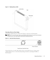
.... Figure 1-3. NOTE: Do not connect the power cable to a power source in the steps detailed in Starting and Configuring the Device. Back-Panel Power Connectors PowerConnect Switch Rear View Power Connector Connect the device to an AC outlet.
.... Figure 1-3. NOTE: Do not connect the power cable to a power source in the steps detailed in Starting and Configuring the Device. Back-Panel Power Connectors PowerConnect Switch Rear View Power Connector Connect the device to an AC outlet.

Getting Started Guide
Page 12
...192.168.2.1) and subnet mask (255.255.255.0). • The PowerConnect device booted successfully. NOTE: Before proceeding, read the release notes for configuring the default route. 10 Getting Started Guide Booting the Switch When the device is connected to be managed • The IP ...revision of the user documentation from the Dell Support website at support.dell.com. The boot process runs approximately 90 seconds. NOTE: Obtain the following assumptions: • The PowerConnect device is configured with the default settings, as an unmanaged switch. You can download the release notes ...
...192.168.2.1) and subnet mask (255.255.255.0). • The PowerConnect device booted successfully. NOTE: Before proceeding, read the release notes for configuring the default route. 10 Getting Started Guide Booting the Switch When the device is connected to be managed • The IP ...revision of the user documentation from the Dell Support website at support.dell.com. The boot process runs approximately 90 seconds. NOTE: Obtain the following assumptions: • The PowerConnect device is configured with the default settings, as an unmanaged switch. You can download the release notes ...

Getting Started Guide
Page 13
To do so, enter the IP address of the device in the URL field of the switch. NOTE: This getting started guide provides information on your documenatation CD. NOTE: The web management interface supports the following web browsers: Microsoft Internet Explorer... or above. 2 In the Web user interface, Click IP Addressing. Getting Started Guide 11 For more information on the management capabilities of the switch, please refer the PowerConnect 27xx Series User's Guide found on the steps necessary for basic setup of a web browser. The device is configured. To configure the device: ...
To do so, enter the IP address of the device in the URL field of the switch. NOTE: This getting started guide provides information on your documenatation CD. NOTE: The web management interface supports the following web browsers: Microsoft Internet Explorer... or above. 2 In the Web user interface, Click IP Addressing. Getting Started Guide 11 For more information on the management capabilities of the switch, please refer the PowerConnect 27xx Series User's Guide found on the steps necessary for basic setup of a web browser. The device is configured. To configure the device: ...
Readme
Page 3
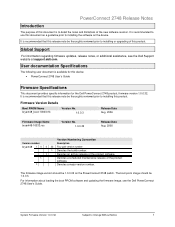
...a guideline prior to installing the software on the PowerConnect 2748 switch. For information about loading the boot PROM software and updating the firmware image, see the Dell Support website at support.dell.com. It is recommended that this release note be...User documentation Specifications The following user document is available for this device: • PowerConnect 2748 User's Guide Firmware Specifications This document provides specific information for the Dell PowerConnect 2748 product, firmware version 1.0.0.32. Global Support For information regarding firmware updates, release...
...a guideline prior to installing the software on the PowerConnect 2748 switch. For information about loading the boot PROM software and updating the firmware image, see the Dell Support website at support.dell.com. It is recommended that this release note be...User documentation Specifications The following user document is available for this device: • PowerConnect 2748 User's Guide Firmware Specifications This document provides specific information for the Dell PowerConnect 2748 product, firmware version 1.0.0.32. Global Support For information regarding firmware updates, release...

User's Guide
Page 3
... Address Supported Features 11 Layer 2 Features 11 VLAN Supported Features 12 Class of Service (CoS) Features 12 Ethernet Switch Management Features 13 Port Default Settings 13 2 Hardware Description Switch Port Configurations 15 PowerConnect 2708/2716/2724/2748 Front Panel Port Description . . . . 15 Physical Dimensions 19 LED Definitions 19 Power LED 19 Managed Mode LED...
... Address Supported Features 11 Layer 2 Features 11 VLAN Supported Features 12 Class of Service (CoS) Features 12 Ethernet Switch Management Features 13 Port Default Settings 13 2 Hardware Description Switch Port Configurations 15 PowerConnect 2708/2716/2724/2748 Front Panel Port Description . . . . 15 Physical Dimensions 19 LED Definitions 19 Power LED 19 Managed Mode LED...
User's Guide
Page 4
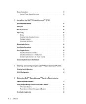
Power Connectors 24 Internal Power Supply Connector 24 3 Installing the Dell™ PowerConnect™ 27XX Installation Precautions 25 Overview 25 Site Requirements 26 Unpacking 26 Safety 26 Handling Static...the Network 32 4 Starting and Configuring the Dell™ PowerConnect™ 27XX Viewing Switch Operation 33 Initial Configuration 33 5 Using the Dell™ OpenManage™ Switch Administrator Understanding the Interface 37 Using the OpenManage Switch Administrator Buttons 39 Information Buttons 39 PowerConnect Switch Management Buttons 39 Starting the Application 40 ...
Power Connectors 24 Internal Power Supply Connector 24 3 Installing the Dell™ PowerConnect™ 27XX Installation Precautions 25 Overview 25 Site Requirements 26 Unpacking 26 Safety 26 Handling Static...the Network 32 4 Starting and Configuring the Dell™ PowerConnect™ 27XX Viewing Switch Operation 33 Initial Configuration 33 5 Using the Dell™ OpenManage™ Switch Administrator Understanding the Interface 37 Using the OpenManage Switch Administrator Buttons 39 Information Buttons 39 PowerConnect Switch Management Buttons 39 Starting the Application 40 ...

User's Guide
Page 5
Resetting the Device 41 Displaying Configuration on Demand 42 6 Configuring System Information Defining Switch Information 43 Viewing the Switch Status 43 Viewing System IP Address 44 Defining Interface Configuration 47 Viewing Jumbo Frames 49 Creating VLAN Membership 50 Defining VLAN Interface Settings 51 Configuring ...
Resetting the Device 41 Displaying Configuration on Demand 42 6 Configuring System Information Defining Switch Information 43 Viewing the Switch Status 43 Viewing System IP Address 44 Defining Interface Configuration 47 Viewing Jumbo Frames 49 Creating VLAN Membership 50 Defining VLAN Interface Settings 51 Configuring ...
User's Guide
Page 7
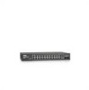
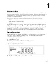
... connectivity. These PowerConnect devices are ideal for installing, configuring and maintaining the PowerConnect 2708, PowerConnect 2716, PowerConnect 2724, and PowerConnect 2748 Webmanaged Gigabit Ethernet switches. The switches are managed by Dell's OpenManage Switch Administrator. 8 1-Gigabit Ethernet Ports The following figure illustrates the PowerConnect 2708 front panel. Figure 1-1. System Description This section describes the hardware configurations of the PowerConnect 2708, PowerConnect 2716, PowerConnect 2724, and PowerConnect 2748.
... connectivity. These PowerConnect devices are ideal for installing, configuring and maintaining the PowerConnect 2708, PowerConnect 2716, PowerConnect 2724, and PowerConnect 2748 Webmanaged Gigabit Ethernet switches. The switches are managed by Dell's OpenManage Switch Administrator. 8 1-Gigabit Ethernet Ports The following figure illustrates the PowerConnect 2708 front panel. Figure 1-1. System Description This section describes the hardware configurations of the PowerConnect 2708, PowerConnect 2716, PowerConnect 2724, and PowerConnect 2748.
User's Guide
Page 8
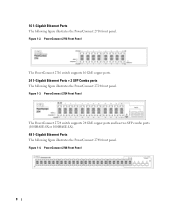
... The following figure illustrates the PowerConnect 2716 front panel. 16 1-Gigabit Ethernet Ports The following figure illustrates the PowerConnect 2748 front panel. Figure 1-3. Figure 1-2. Figure 1-4. PowerConnect 2748 Front Panel 8 PowerConnect 2716 Front Panel The PowerConnect 2716 switch supports 16 GbE copper ports. 24 1-Gigabit Ethernet Ports + 2 SFP Combo ports The following figure illustrates the PowerConnect 2724 front panel.
... The following figure illustrates the PowerConnect 2716 front panel. 16 1-Gigabit Ethernet Ports The following figure illustrates the PowerConnect 2748 front panel. Figure 1-3. Figure 1-2. Figure 1-4. PowerConnect 2748 Front Panel 8 PowerConnect 2716 Front Panel The PowerConnect 2716 switch supports 16 GbE copper ports. 24 1-Gigabit Ethernet Ports + 2 SFP Combo ports The following figure illustrates the PowerConnect 2724 front panel.

User's Guide
Page 9
..., the user presses the Managed Mode button. The user may enable or disable this applies to links operating at all ports is pressed, the switch enters Unmanaged Mode. • Secure Mode (PowerConnect 2748 only) - The default status on the whole system. From Unmanaged Mode, when the Managed Mode button is pressed, the...
..., the user presses the Managed Mode button. The user may enable or disable this applies to links operating at all ports is pressed, the switch enters Unmanaged Mode. • Secure Mode (PowerConnect 2748 only) - The default status on the whole system. From Unmanaged Mode, when the Managed Mode button is pressed, the...
User's Guide
Page 10
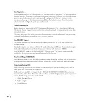
...). This feature is crossed or straight through. The auto negotiation function provides the means to exchange information between two Ethernet switches that transmission must be turned off by transporting the same data using less frames. The Jumbo Frames Support feature, utilizes the...Status • Cable Length • Fault-Distance 10 Auto Negotiation Auto negotiation allows an Ethernet switch to advertise modes of their transmission capabilities. AutoMDI/MDIX Support The switch automatically detects whether the cable connected to an RJ-45 port is automatically enabled for server-...
...). This feature is crossed or straight through. The auto negotiation function provides the means to exchange information between two Ethernet switches that transmission must be turned off by transporting the same data using less frames. The Jumbo Frames Support feature, utilizes the...Status • Cable Length • Fault-Distance 10 Auto Negotiation Auto negotiation allows an Ethernet switch to advertise modes of their transmission capabilities. AutoMDI/MDIX Support The switch automatically detects whether the cable connected to an RJ-45 port is automatically enabled for server-...

User's Guide
Page 11
... Multicast frames are forwarded based only on their destination MAC address). MAC Address Supported Features MAC Address Capacity Support The PowerConnect 2708, 2716, and 2724 switches support a total of 8K MAC addresses, and the PowerConnect 2748 supports a total of time are forwarded based on their destination MAC address only, regardless of all ports on...
... Multicast frames are forwarded based only on their destination MAC address). MAC Address Supported Features MAC Address Capacity Support The PowerConnect 2708, 2716, and 2724 switches support a total of 8K MAC addresses, and the PowerConnect 2748 supports a total of time are forwarded based on their destination MAC address only, regardless of all ports on...

User's Guide
Page 12
... download file name. DHCP is then used to provide the switch system with up to download a valid runtime image. The information replied is an extension to BootP. Link Aggregation The PowerConnect 2708/2716/2724/2748 switches support up to four member ports to form a single Link... Aggregated Group (LAG). Each of switching ports that comprise a single broadcast domain. Port Based Virtual LANs (VLANs)...
... download file name. DHCP is then used to provide the switch system with up to download a valid runtime image. The information replied is an extension to BootP. Link Aggregation The PowerConnect 2708/2716/2724/2748 switches support up to four member ports to form a single Link... Aggregated Group (LAG). Each of switching ports that comprise a single broadcast domain. Port Based Virtual LANs (VLANs)...
User's Guide
Page 13
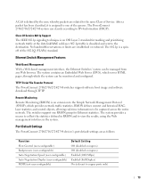
...Protocol The PowerConnect 2708/2716/2724/2748 switches support software boot image and software download through which provides network traffic statistics. The system provides a means to collect the statistics defined in RMON and to be captured across the entire network. The PowerConnect 2708/2716/2724/2748 ...the 802.1Q (VLANs) standard. The switches support one of Service. After a packet has been classified, it is defined by the user, whereby packets are related to copper ports only) 13 Port Default Settings The PowerConnect 2708/2716/2724/2748 devices's port default settings are ...
...Protocol The PowerConnect 2708/2716/2724/2748 switches support software boot image and software download through which provides network traffic statistics. The system provides a means to collect the statistics defined in RMON and to be captured across the entire network. The PowerConnect 2708/2716/2724/2748 ...the 802.1Q (VLANs) standard. The switches support one of Service. After a packet has been classified, it is defined by the user, whereby packets are related to copper ports only) 13 Port Default Settings The PowerConnect 2708/2716/2724/2748 devices's port default settings are ...

User's Guide
Page 15
...), and flow control. Figure 2-1. On each port there are numbered 1 to 8, top down and left side of the PowerConnect 2708/2716/2724/2748 switches. The Power LED on the front panel indicates whether the device is the Managed Mode LED which are LEDs (Light Emitting ...Mbps optical ports can operate at 1000 Mbps, full-duplex mode. 2 Hardware Description Switch Port Configurations PowerConnect 2708/2716/2724/2748 Front Panel Port Description The Dell™ PowerConnect™ 2708, 2716, 2724 and 2748 switches use 10/100/1000BASE-T ports on the front panel for connecting to indicate the...
...), and flow control. Figure 2-1. On each port there are numbered 1 to 8, top down and left side of the PowerConnect 2708/2716/2724/2748 switches. The Power LED on the front panel indicates whether the device is the Managed Mode LED which are LEDs (Light Emitting ...Mbps optical ports can operate at 1000 Mbps, full-duplex mode. 2 Hardware Description Switch Port Configurations PowerConnect 2708/2716/2724/2748 Front Panel Port Description The Dell™ PowerConnect™ 2708, 2716, 2724 and 2748 switches use 10/100/1000BASE-T ports on the front panel for connecting to indicate the...


