Getting Started Guide
Page 11
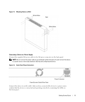
... Drilled Holes Connecting a Device to a Power Supply Connect the supplied AC power cable to a power source in the steps detailed in Starting and Configuring the Device. You will connect the device to the AC power connector on the front panel. Getting Started Guide 9 Figure 1-4. Back-Panel Power Connectors PowerConnect Switch Rear View Power Connector Connect the device to a grounded...
... Drilled Holes Connecting a Device to a Power Supply Connect the supplied AC power cable to a power source in the steps detailed in Starting and Configuring the Device. You will connect the device to the AC power connector on the front panel. Getting Started Guide 9 Figure 1-4. Back-Panel Power Connectors PowerConnect Switch Rear View Power Connector Connect the device to a grounded...

Getting Started Guide
Page 12
... user documentation from the Dell Support website at support.dell.com. NOTE: It is configured with the pre configured default IP (192.168.2.1) and subnet mask (255.255.255.0). • The PowerConnect device booted successfully. If POST passes successfully, the System and the Power LEDs glow and a...operational before completely booting. A power-on the enclosed CD. To begin using the device, it is initialized and checks hardware components to be assigned to the VLAN 1 interface through which the device is to determine if the device is being supplied to configure the device with...
... user documentation from the Dell Support website at support.dell.com. NOTE: It is configured with the pre configured default IP (192.168.2.1) and subnet mask (255.255.255.0). • The PowerConnect device booted successfully. If POST passes successfully, the System and the Power LEDs glow and a...operational before completely booting. A power-on the enclosed CD. To begin using the device, it is initialized and checks hardware components to be assigned to the VLAN 1 interface through which the device is to determine if the device is being supplied to configure the device with...
User's Guide
Page 4
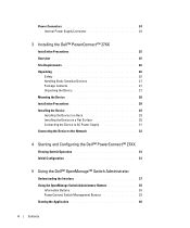
Power Connectors 24 Internal Power Supply Connector 24 3 Installing the Dell™ PowerConnect™ 27XX Installation Precautions 25 Overview 25 Site Requirements 26 Unpacking 26 Safety 26 Handling Static Sensitive Devices 27 Package Contents...the Device on a Flat Surface 30 Connecting the Device to AC Power Supply 31 Connecting the Device to the Network 32 4 Starting and Configuring the Dell™ PowerConnect™ 27XX Viewing Switch Operation 33 Initial Configuration 33 5 Using the Dell™ OpenManage™ Switch Administrator Understanding the Interface 37 Using the...
Power Connectors 24 Internal Power Supply Connector 24 3 Installing the Dell™ PowerConnect™ 27XX Installation Precautions 25 Overview 25 Site Requirements 26 Unpacking 26 Safety 26 Handling Static Sensitive Devices 27 Package Contents...the Device on a Flat Surface 30 Connecting the Device to AC Power Supply 31 Connecting the Device to the Network 32 4 Starting and Configuring the Dell™ PowerConnect™ 27XX Viewing Switch Operation 33 Initial Configuration 33 5 Using the Dell™ OpenManage™ Switch Administrator Understanding the Interface 37 Using the...

User's Guide
Page 18
...45 port will be used on a combo port, and utilizes the information in all the control interfaces. The back panel contains an AC Power Supply Interface. Figure 2-8. PowerConnect 2748 Back Panel 18 NOTE: The system can be disabled. If both RJ-45 and SFP ports are determined by the physical connection ...used. Figure 2-7. PowerConnect 2748 Front Panel On the front panel, there are numbered 1 to 48, top down and left to right. There are four SFP (Small FormFactor...
...45 port will be used on a combo port, and utilizes the information in all the control interfaces. The back panel contains an AC Power Supply Interface. Figure 2-8. PowerConnect 2748 Back Panel 18 NOTE: The system can be disabled. If both RJ-45 and SFP ports are determined by the physical connection ...used. Figure 2-7. PowerConnect 2748 Front Panel On the front panel, there are numbered 1 to 48, top down and left to right. There are four SFP (Small FormFactor...
User's Guide
Page 19
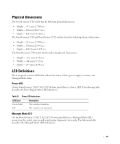
... the switch node as well as indicating diagnostic test results. Power LED Indications LED Color Green Solid Off Description The switch is not turned on . The switch is turned on . Table 2-1. The following table describes the Power Supply status LED indications. Managed Mode LED On the PowerConnect 2708/2716/2724/2748 front panel there is...
... the switch node as well as indicating diagnostic test results. Power LED Indications LED Color Green Solid Off Description The switch is not turned on . The switch is turned on . Table 2-1. The following table describes the Power Supply status LED indications. Managed Mode LED On the PowerConnect 2708/2716/2724/2748 front panel there is...
User's Guide
Page 24
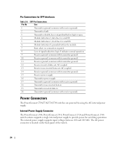
... data in 20 Transmitter ground (common with receiver ground) Power Connectors The PowerConnect 2708/2716/2724/2748 switches are powered by using the AC internal power supply. Internal Power Supply Connector The PowerConnect 2708, PowerConnect 2716, PowerConnect 2724 and PowerConnect 2748 switch systems supports a single internal power supply to provide power for serial ID. 6 Module definition 0; The internal power supply supports input voltages between 100 and 240 VAC.
... data in 20 Transmitter ground (common with receiver ground) Power Connectors The PowerConnect 2708/2716/2724/2748 switches are powered by using the AC internal power supply. Internal Power Supply Connector The PowerConnect 2708, PowerConnect 2716, PowerConnect 2724 and PowerConnect 2748 switch systems supports a single internal power supply to provide power for serial ID. 6 Module definition 0; The internal power supply supports input voltages between 100 and 240 VAC.
User's Guide
Page 26
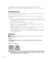
Site Requirements The PowerConnect 2708/2716/2724/2748 devices can be mounted in a standard equipment rack, placed on a tabletop, or mounted on a power supply or any part that has the following site requirements: • Power - Figure 3-1. The device is routed to Dell. Cabling is installed within 1.5 m (5 feet) of damage immediately to avoid sources of electrical noise such...
Site Requirements The PowerConnect 2708/2716/2724/2748 devices can be mounted in a standard equipment rack, placed on a tabletop, or mounted on a power supply or any part that has the following site requirements: • Power - Figure 3-1. The device is routed to Dell. Cabling is installed within 1.5 m (5 feet) of damage immediately to avoid sources of electrical noise such...

User's Guide
Page 28
...8226; Ensure that the device is not exposed to water. • Ensure that the device does not overload the power circuits, wiring, and over . • Ensure that the power source circuits are not blocked. • Do not push foreign objects into the device, as it from becoming ...service technicians only. • Ensure that the power cable, extension cable, and/or plug is not damaged. • Ensure that the device is not exposed to the PowerConnect 2708/2716/2724/2748 devices. To determine the possibility of overloading the supply circuits, add together the ampere ratings of the...
...8226; Ensure that the device is not exposed to water. • Ensure that the device does not overload the power circuits, wiring, and over . • Ensure that the power source circuits are not blocked. • Do not push foreign objects into the device, as it from becoming ...service technicians only. • Ensure that the power cable, extension cable, and/or plug is not damaged. • Ensure that the device is not exposed to the PowerConnect 2708/2716/2724/2748 devices. To determine the possibility of overloading the supply circuits, add together the ampere ratings of the...

User's Guide
Page 31
Mounting Device on a Wall Connecting the Device to the AC connector located on the back panel. 31 7 Secure the unit to the wall with safety ground connected, connect the power cable to AC Power Supply 1 Using a 5-foot (1.5 m) standard power cable with screws (not provided). Figure 3-4. Ensure that the ventilation holes are not obstructed.
Mounting Device on a Wall Connecting the Device to the AC connector located on the back panel. 31 7 Secure the unit to the wall with safety ground connected, connect the power cable to AC Power Supply 1 Using a 5-foot (1.5 m) standard power cable with screws (not provided). Figure 3-4. Ensure that the ventilation holes are not obstructed.
User's Guide
Page 63
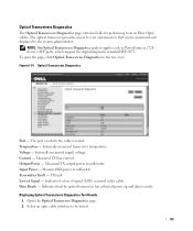
...supply voltage. Current - Data Ready - Measured TX output power in milliwatts. Measured RX power in milliwatts. Measured TX bias current. TX fault Loss of signal (LOS) occurred in the tree view. Indicates if a loss of Signal - Indicates that can be tested. 63 Figure 6-14. Optical Transceivers Diagnostics Port - Voltage - Input Power... Power - Transmitter Fault - Displaying Optical Transceivers Diagnostics Test Results 1 Open the Optical Transceiver Diagnostics page. 2 Select an optic cable interface to be monitored and displayed to PowerConnect 2724 ...
...supply voltage. Current - Data Ready - Measured TX output power in milliwatts. Measured RX power in milliwatts. Measured TX bias current. TX fault Loss of signal (LOS) occurred in the tree view. Indicates if a loss of Signal - Indicates that can be tested. 63 Figure 6-14. Optical Transceivers Diagnostics Port - Voltage - Input Power... Power - Transmitter Fault - Displaying Optical Transceivers Diagnostics Test Results 1 Open the Optical Transceiver Diagnostics page. 2 Select an optic cable interface to be monitored and displayed to PowerConnect 2724 ...


