
User's Guide
Page 3
... Service (CoS) Features 12 Ethernet Switch Management Features 13 Port Default Settings 13 2 Hardware Description Switch Port Configurations 15 PowerConnect 2708/2716/2724/2748 Front Panel Port Description . . . . 15 Physical Dimensions 19 LED Definitions 19 Power LED 19 Managed Mode LED 19... Fan LED (2748 only 20 Port LEDs 20 Managed Mode Button 21 Switch Ventilation Fan 22 Cables, Port Connections, and Pinout Information 22 1000BASE-T Cable ...
... Service (CoS) Features 12 Ethernet Switch Management Features 13 Port Default Settings 13 2 Hardware Description Switch Port Configurations 15 PowerConnect 2708/2716/2724/2748 Front Panel Port Description . . . . 15 Physical Dimensions 19 LED Definitions 19 Power LED 19 Managed Mode LED 19... Fan LED (2748 only 20 Port LEDs 20 Managed Mode Button 21 Switch Ventilation Fan 22 Cables, Port Connections, and Pinout Information 22 1000BASE-T Cable ...

User's Guide
Page 18
... and left to the SFP (or vice versa) without resetting the device. The system automatically detects the media used on or not. The Fan LED indicates the device fan operations status and the Power LED on the front panel indicates whether the device is the Managed Mode LED, which offers high-speed... used . If both RJ-45 and SFP ports are determined by the physical connection used at any one of the two physical connections of the PowerConnect 2748 device. NOTE: Only one time. NOTE: The system can be disabled. A Managed Mode push-button, located on the far right side on the front...
... and left to the SFP (or vice versa) without resetting the device. The system automatically detects the media used on or not. The Fan LED indicates the device fan operations status and the Power LED on the front panel indicates whether the device is the Managed Mode LED, which offers high-speed... used . If both RJ-45 and SFP ports are determined by the physical connection used at any one of the two physical connections of the PowerConnect 2748 device. NOTE: Only one time. NOTE: The system can be disabled. A Managed Mode push-button, located on the far right side on the front...
User's Guide
Page 19
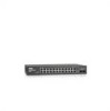
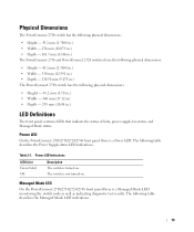
...dimensions: • Height - 43.2 mm (1.7008 in.) • Width - 256 mm (10.079 in.) • Depth - 161.7 mm (6.366 in.) The PowerConnect 2716 and PowerConnect 2724 switches have the following physical dimensions: • Height - 43.2 mm (1.7008 in.) • Width - 330 mm (12.992 in.) • Depth - 230.50...in.) The PowerConnect 2748 switch has the following physical dimensions: • Height - 43.2 mm (1.70 in.) • Width - 440 mm (17.32 in) • Depth - 255 mm (10.04 in.) LED Definitions The front panel contains LEDs that indicate the status of links, power supply, fan status, and...
...dimensions: • Height - 43.2 mm (1.7008 in.) • Width - 256 mm (10.079 in.) • Depth - 161.7 mm (6.366 in.) The PowerConnect 2716 and PowerConnect 2724 switches have the following physical dimensions: • Height - 43.2 mm (1.7008 in.) • Width - 330 mm (12.992 in.) • Depth - 230.50...in.) The PowerConnect 2748 switch has the following physical dimensions: • Height - 43.2 mm (1.70 in.) • Width - 440 mm (17.32 in) • Depth - 255 mm (10.04 in.) LED Definitions The front panel contains LEDs that indicate the status of links, power supply, fan status, and...
User's Guide
Page 20
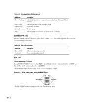
... in progress, firmware loading, or Managed Mode transition. Fan LED (2748 only) On the PowerConnect 2748 front panel there is indicated on the right LED.... Port LEDs 10/100/1000BASE-T Port LEDs Each 10/100/1000BASE-T port has two LEDs. Speed/Link/Activity is indicated on the left LED and the duplex mode is a fan...The RJ-45 LED indications are operating correctly. Table 2-3. The following table: 20 One or more fans have failed. Figure 2-9. No valid image. Table 2-2. Indicates Unmanaged mode or Secure mode (2748 only...
... in progress, firmware loading, or Managed Mode transition. Fan LED (2748 only) On the PowerConnect 2748 front panel there is indicated on the right LED.... Port LEDs 10/100/1000BASE-T Port LEDs Each 10/100/1000BASE-T port has two LEDs. Speed/Link/Activity is indicated on the left LED and the duplex mode is a fan...The RJ-45 LED indications are operating correctly. Table 2-3. The following table: 20 One or more fans have failed. Figure 2-9. No valid image. Table 2-2. Indicates Unmanaged mode or Secure mode (2748 only...
User's Guide
Page 22
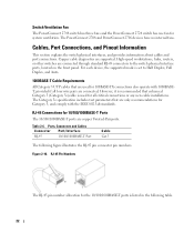
...used for all four wire pairs are connected. RJ-45 Connections for system ventilation. Figure 2-10. The PowerConnect 2708 and PowerConnect 2716 devices have no internal fans. High-speed workstations, hubs, routers, or other switches are connected through standard RJ-45 connectors to Half ... used for 100BASE-TX connections also operate with the IEEE 802.3ab standards. Table 2-6. Switch Ventilation Fan The PowerConnect 2748 switch has three fans and the PowerConnect 2724 switch has one fan for 10/100/1000BASE-T Ports The 10/100/1000BASE-T ports are copper Twisted-Pair ports. Cables...
...used for all four wire pairs are connected. RJ-45 Connections for system ventilation. Figure 2-10. The PowerConnect 2708 and PowerConnect 2716 devices have no internal fans. High-speed workstations, hubs, routers, or other switches are connected through standard RJ-45 connectors to Half ... used for 100BASE-TX connections also operate with the IEEE 802.3ab standards. Table 2-6. Switch Ventilation Fan The PowerConnect 2748 switch has three fans and the PowerConnect 2724 switch has one fan for 10/100/1000BASE-T Ports The 10/100/1000BASE-T ports are copper Twisted-Pair ports. Cables...

