Dell OptiPlex 9010 All-In-One Touch Owner's Manual
Page 3
... Your Computer...8 After Working Inside Your Computer...8 2 Removing and Installing Components 9 Recommended Tools...9 Removing the VESA Stand...9 Installing the VESA Stand...10 Removing the Back Cover...10 Installing the Back Cover...11 Removing the Memory...11 Installing the Memory...12 Removing the VESA Mount Bracket...12 Installing the VESA Mount Bracket...13 Removing the Touchscreen Board...13...
... Your Computer...8 After Working Inside Your Computer...8 2 Removing and Installing Components 9 Recommended Tools...9 Removing the VESA Stand...9 Installing the VESA Stand...10 Removing the Back Cover...10 Installing the Back Cover...11 Removing the Memory...11 Installing the Memory...12 Removing the VESA Mount Bracket...12 Installing the VESA Mount Bracket...13 Removing the Touchscreen Board...13...
Dell OptiPlex 9010 All-In-One Touch Owner's Manual
Page 11
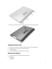
Tighten the screws to secure the back cover to the computer. 3. Removing the Memory 1. Follow the procedures in Before Working Inside Your Computer. 2. Installing the Back Cover 1. Follow the procedures in After Working Inside Your Computer. 4. Place the cover on the back of the computer using the notches near the input/output panel. 2. Install the VESA stand. 4. Remove the: a) VESA stand b) back cover 11 Lift the cover and remove it from the computer using the notches near the input/output panel.
Tighten the screws to secure the back cover to the computer. 3. Removing the Memory 1. Follow the procedures in Before Working Inside Your Computer. 2. Installing the Back Cover 1. Follow the procedures in After Working Inside Your Computer. 4. Place the cover on the back of the computer using the notches near the input/output panel. 2. Install the VESA stand. 4. Remove the: a) VESA stand b) back cover 11 Lift the cover and remove it from the computer using the notches near the input/output panel.
Dell OptiPlex 9010 All-In-One Touch Owner's Manual
Page 12
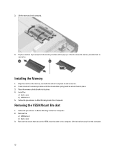
... that secure the VESA mount bracket to secure them in the system-board connector. 2. Lift the memory shield outwards. 4. Install the: a) back cover b) VESA stand 5. Lift and remove the memory module from its place. 4. Press down on the memory-card with the tab in place. 3. Remove the: a) VESA stand b) back cover 3. Lift the bracket...
... that secure the VESA mount bracket to secure them in the system-board connector. 2. Lift the memory shield outwards. 4. Install the: a) back cover b) VESA stand 5. Lift and remove the memory module from its place. 4. Press down on the memory-card with the tab in place. 3. Remove the: a) VESA stand b) back cover 3. Lift the bracket...
Dell OptiPlex 9010 All-In-One Touch Owner's Manual
Page 31
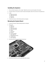
...notches. Thread the cables on the computer. Remove the: a) VESA stand b) back cover c) VESA mount bracket d) system-board shield e) memory f) optical drive g) hard drive h) heat-sink assembly i) power supply unit j) input/output board shield k) converter board l) power-supply fan... 3. Follow the procedures in Before Working Inside Your Computer. 2. Follow the procedures in After Working Inside Your Computer. Installing the Speakers 1. Install: a) system-board shield b) VESA mount bracket c) back cover d) VESA stand 4. Connect the right and left speaker cables to...
...notches. Thread the cables on the computer. Remove the: a) VESA stand b) back cover c) VESA mount bracket d) system-board shield e) memory f) optical drive g) hard drive h) heat-sink assembly i) power supply unit j) input/output board shield k) converter board l) power-supply fan... 3. Follow the procedures in Before Working Inside Your Computer. 2. Follow the procedures in After Working Inside Your Computer. Installing the Speakers 1. Install: a) system-board shield b) VESA mount bracket c) back cover d) VESA stand 4. Connect the right and left speaker cables to...
Dell OptiPlex 9010 All-In-One Touch Owner's Manual
Page 33
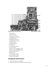
... socket 13. Touch panel connector 4. SATA ODD power connector 8. Memory connector (SODIMM socket B) 14. Memory connector (SODIMM socket A) 15. Mini-PCI socket 17. Place the system board on the computer. 2. PSU connector 2. SATA HDD connector 6. SATA HDD power connector 7. Converter board connector Installing the System Board 1. Tighten the screws to secure the system...
... socket 13. Touch panel connector 4. SATA ODD power connector 8. Memory connector (SODIMM socket B) 14. Memory connector (SODIMM socket A) 15. Mini-PCI socket 17. Place the system board on the computer. 2. PSU connector 2. SATA HDD connector 6. SATA HDD power connector 7. Converter board connector Installing the System Board 1. Tighten the screws to secure the system...
Dell OptiPlex 9010 All-In-One Touch Owner's Manual
Page 34
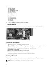
Install: a) power-supply fan b) converter board c) input/output board shield d) power supply unit e) heat-sink assembly f) hard drive g) optical drive h) memory i) system-board shield j) VESA mount bracket k) back cover l) VESA stand 4. Jumper Settings The system's software security features ... steps to its original position. 6. Follow the procedures in step 2. 7. Clearing the CMOS Password 1. Wait for 3-4 seconds. Install all the components removed in After Working Inside Your Computer. The PASSWORD jumper enables or disables these password features and clears any password...
Install: a) power-supply fan b) converter board c) input/output board shield d) power supply unit e) heat-sink assembly f) hard drive g) optical drive h) memory i) system-board shield j) VESA mount bracket k) back cover l) VESA stand 4. Jumper Settings The system's software security features ... steps to its original position. 6. Follow the procedures in step 2. 7. Clearing the CMOS Password 1. Wait for 3-4 seconds. Install all the components removed in After Working Inside Your Computer. The PASSWORD jumper enables or disables these password features and clears any password...
Dell OptiPlex 9010 All-In-One Touch Owner's Manual
Page 35
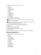
... system-board shield e) memory f) optical drive g) hard drive h) heat-sink assembly i) power supply unit j) input/output board shield k) converter board l) power-supply fan 3. NOTE: The existing passwords are not disabled (erased) until the computer boots without the jumper. 5. Install all the components removed...boots. 6. Follow the procedures in step 2. Removing the Display Panel 1. Remove the PSWD jumper from the electrical outlet. 8. Install all the components removed in After Working Inside Your Computer. 12. Follow the procedures in step 8. 11. Follow the procedures ...
... system-board shield e) memory f) optical drive g) hard drive h) heat-sink assembly i) power supply unit j) input/output board shield k) converter board l) power-supply fan 3. NOTE: The existing passwords are not disabled (erased) until the computer boots without the jumper. 5. Install all the components removed...boots. 6. Follow the procedures in step 2. Removing the Display Panel 1. Remove the PSWD jumper from the electrical outlet. 8. Install all the components removed in After Working Inside Your Computer. 12. Follow the procedures in step 8. 11. Follow the procedures ...
Dell OptiPlex 9010 All-In-One Touch Owner's Manual
Page 44
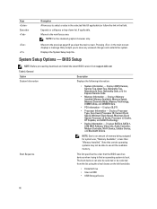
NOTE: For the standard graphics browser only. Displays Memory Installed, Memory Available, Memory Speed, Memory Channels Mode, Memory Technology, DIMM A Size, and DIMM B Size . • PCI Information - Displays SATA-0, SATA-1, LOM MAC Address, Video info, Audio Controller, ... or de-selected from support.dell.com Table 2. The boot devices can also be able to use , "Memory Available", is less than "Memory Installed". Displays SLOT1. • Processor Information - Moves to an amount of memory being assigned for system use all the available memory. Note that the BIOS searches...
NOTE: For the standard graphics browser only. Displays Memory Installed, Memory Available, Memory Speed, Memory Channels Mode, Memory Technology, DIMM A Size, and DIMM B Size . • PCI Information - Displays SATA-0, SATA-1, LOM MAC Address, Video info, Audio Controller, ... or de-selected from support.dell.com Table 2. The boot devices can also be able to use , "Memory Available", is less than "Memory Installed". Displays SLOT1. • Processor Information - Moves to an amount of memory being assigned for system use all the available memory. Note that the BIOS searches...
Dell OptiPlex 9010 All-In-One Touch Owner's Manual
Page 57
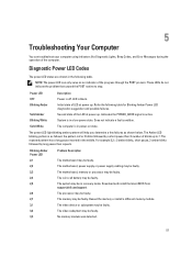
...then X number of blinks up to stop. The motherboard, power supply or power supply cabling may be faulty. Download and install the latest BIOS from support.dell.com/support. The memory may be faulty. LED is active. The system may be faulty. NOTE: The power LED can troubleshoot your computer using indicators... may be faulty. Power LED OFF Blinking Amber Solid Amber Blinking White Solid White Description Power is in a low power state. Reseat the memory or install a different memory module. Diagnostic Power LED Codes The power LED states are shown in the middle.
...then X number of blinks up to stop. The motherboard, power supply or power supply cabling may be faulty. Download and install the latest BIOS from support.dell.com/support. The memory may be faulty. LED is active. The system may be faulty. NOTE: The power LED can troubleshoot your computer using indicators... may be faulty. Power LED OFF Blinking Amber Solid Amber Blinking White Solid White Description Power is in a low power state. Reseat the memory or install a different memory module. Diagnostic Power LED Codes The power LED states are shown in the middle.


