Dell OptiPlex 9010 All-In-One Touch Owner's Manual
Page 3
...-Board Shield...15 Installing the System-Board Shield...15 Removing the Coin-Cell Battery...15 Installing the Coin-Cell Battery...16 Removing the Optical Drive...16 Installing the Optical Drive...18 Removing the Hard Drive...18 Installing the Hard Drive...19 Removing the Intrusion Switch...19 Installing the Intrusion Switch...20 Removing the Wireless Local Area Network (WLAN) Card 21 Installing...
...-Board Shield...15 Installing the System-Board Shield...15 Removing the Coin-Cell Battery...15 Installing the Coin-Cell Battery...16 Removing the Optical Drive...16 Installing the Optical Drive...18 Removing the Hard Drive...18 Installing the Hard Drive...19 Removing the Intrusion Switch...19 Installing the Intrusion Switch...20 Removing the Wireless Local Area Network (WLAN) Card 21 Installing...
Dell OptiPlex 9010 All-In-One Touch Owner's Manual
Page 18
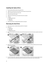
... hard drive, remove the screws that secure the hard drive to the computer. 6. Removing the Hard Drive 1. Remove the: a) VESA stand b) back cover c) VESA mount bracket 3. Tighten the screws that secure the hard-drive case to the optical drive. 3. Slide the hard drive from the computer. 5. Remove the screws that secure the optical drive to the hard-drive bracket. Slide and lift the hard-drive bracket away from the hard-drive bracket...
... hard drive, remove the screws that secure the hard drive to the computer. 6. Removing the Hard Drive 1. Remove the: a) VESA stand b) back cover c) VESA mount bracket 3. Tighten the screws that secure the hard-drive case to the optical drive. 3. Slide the hard drive from the computer. 5. Remove the screws that secure the optical drive to the hard-drive bracket. Slide and lift the hard-drive bracket away from the hard-drive bracket...
Dell OptiPlex 9010 All-In-One Touch Owner's Manual
Page 19
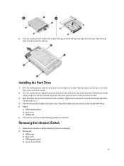
For a 3.5-inch hard drive, slide the hard drive into the hard-drive bracket. Tighten the screws that secure the hard-drive case to the hard-drive bracket. 2. For a 2.5-inch hard drive, tighten the screws that secure the hard drive to the hard drive. Align and place the hard-drive bracket on the hard-drive bracket. 5. Remove the: a) VESA stand b) back cover c) VESA mount bracket d) system-board shield 19 6. Installing the Hard Drive 1. Tighten the...
For a 3.5-inch hard drive, slide the hard drive into the hard-drive bracket. Tighten the screws that secure the hard-drive case to the hard-drive bracket. 2. For a 2.5-inch hard drive, tighten the screws that secure the hard drive to the hard drive. Align and place the hard-drive bracket on the hard-drive bracket. 5. Remove the: a) VESA stand b) back cover c) VESA mount bracket d) system-board shield 19 6. Installing the Hard Drive 1. Tighten the...
Dell OptiPlex 9010 All-In-One Touch Owner's Manual
Page 31
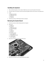
...on the computer. Follow the procedures in Before Working Inside Your Computer. 2. Disconnect any cables connected to the computer. 31 Remove the screws that secure the system board to the system board. 4. Place and align the speakers on the notches. Install...chassis. 2. Tighten the screws to secure the speaker to the connector on the system board. 3. Remove the: a) VESA stand b) back cover c) VESA mount bracket d) system-board shield e) memory f) optical drive g) hard drive h) heat-sink assembly i) power supply unit j) input/output board shield k) converter board l) ...
...on the computer. Follow the procedures in Before Working Inside Your Computer. 2. Disconnect any cables connected to the computer. 31 Remove the screws that secure the system board to the system board. 4. Place and align the speakers on the notches. Install...chassis. 2. Tighten the screws to secure the speaker to the connector on the system board. 3. Remove the: a) VESA stand b) back cover c) VESA mount bracket d) system-board shield e) memory f) optical drive g) hard drive h) heat-sink assembly i) power supply unit j) input/output board shield k) converter board l) ...
Dell OptiPlex 9010 All-In-One Touch Owner's Manual
Page 34
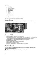
... cover l) VESA stand 4. The PASSWORD jumper enables or disables these password features and clears any password(s) currently in use . Remove the VESA stand, back cover, VESA mount bracket, system-board shield, memory, optical drive, hard drive, heat-sink assembly, power supply unit, input/output board shield, converter board, power-supply fan. 3. Connect your computer...
... cover l) VESA stand 4. The PASSWORD jumper enables or disables these password features and clears any password(s) currently in use . Remove the VESA stand, back cover, VESA mount bracket, system-board shield, memory, optical drive, hard drive, heat-sink assembly, power supply unit, input/output board shield, converter board, power-supply fan. 3. Connect your computer...
Dell OptiPlex 9010 All-In-One Touch Owner's Manual
Page 35
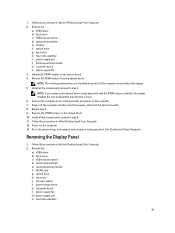
... e) input/output board shield f) WLAN card g) optical drive h) hard drive i) intrusion switch j) power-button board k) converter board l) power-supply fan m) power supply unit n) heat-sink assembly 35 1. Install all the components removed in After Working Inside Your Computer. 12. Follow the ...or setup password. Go to the electrical outlet and power-on the computer. 13. Remove the: a) VESA stand b) back cover c) VESA mount bracket d) system-board shield e) memory f) optical drive g) hard drive h) heat-sink assembly i) power supply unit j) input/output board shield k) converter ...
... e) input/output board shield f) WLAN card g) optical drive h) hard drive i) intrusion switch j) power-button board k) converter board l) power-supply fan m) power supply unit n) heat-sink assembly 35 1. Install all the components removed in After Working Inside Your Computer. 12. Follow the ...or setup password. Go to the electrical outlet and power-on the computer. 13. Remove the: a) VESA stand b) back cover c) VESA mount bracket d) system-board shield e) memory f) optical drive g) hard drive h) heat-sink assembly i) power supply unit j) input/output board shield k) converter ...
Dell OptiPlex 9010 All-In-One Touch Owner's Manual
Page 39
...power-supply fan h) converter board i) power-button board j) intrusion switch k) hard drive l) optical drive m) WLAN card n) input/output board shield o) system-board shield p) VESA mount bracket q) back cover r) VESA stand 9. Remove the: a) VESA stand b) back cover c) VESA mount bracket d) system-board... shield e) input/output board shield f) WLAN card g) optical drive h) hard drive i) intrusion switch j) power button board k) converter board l) ...
...power-supply fan h) converter board i) power-button board j) intrusion switch k) hard drive l) optical drive m) WLAN card n) input/output board shield o) system-board shield p) VESA mount bracket q) back cover r) VESA stand 9. Remove the: a) VESA stand b) back cover c) VESA mount bracket d) system-board... shield e) input/output board shield f) WLAN card g) optical drive h) hard drive i) intrusion switch j) power button board k) converter board l) ...
Dell OptiPlex 9010 All-In-One Touch Owner's Manual
Page 40
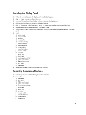
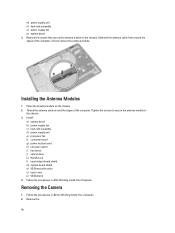
...b) power-supply fan c) heat-sink assembly d) power supply unit e) processor fan f) converter board g) power-button board h) intrusion switch i) hard drive j) optical drive k) WLAN card l) input/output board shield m) system-board shield n) VESA mount bracket o) back cover p) VESA stand 4. Follow the procedures ...Tighten the screws to secure the antenna module to the chassis. Removing the Camera 1. Remove the: 40 Lift and remove the antenna module. Thread the antenna cable around the edges of the computer. Remove the screws that secure the antenna module to the chassis 3. ...
...b) power-supply fan c) heat-sink assembly d) power supply unit e) processor fan f) converter board g) power-button board h) intrusion switch i) hard drive j) optical drive k) WLAN card l) input/output board shield m) system-board shield n) VESA mount bracket o) back cover p) VESA stand 4. Follow the procedures ...Tighten the screws to secure the antenna module to the chassis. Removing the Camera 1. Remove the: 40 Lift and remove the antenna module. Thread the antenna cable around the edges of the computer. Remove the screws that secure the antenna module to the chassis 3. ...
Dell OptiPlex 9010 All-In-One Touch Owner's Manual
Page 41
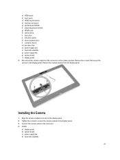
... module from the connector on the display panel. 2. Installing the Camera 1. Remove the screws that secure the camera to its slot on the camera module. Align the camera module to the display panel. ...fan d) heat-sink assembly 41 a) VESA stand b) back cover c) VESA mount bracket d) touchscreen board e) system-board shield f) input/output board shield g) WLAN card h) optical drive i) hard drive j) intrusion switch k) power button board l) converter board m) processor fan n) power supply unit o) heat-sink assembly p) power-supply fan q) system board r) display panel 3. Disconnect...
... module from the connector on the display panel. 2. Installing the Camera 1. Remove the screws that secure the camera to its slot on the camera module. Align the camera module to the display panel. ...fan d) heat-sink assembly 41 a) VESA stand b) back cover c) VESA mount bracket d) touchscreen board e) system-board shield f) input/output board shield g) WLAN card h) optical drive i) hard drive j) intrusion switch k) power button board l) converter board m) processor fan n) power supply unit o) heat-sink assembly p) power-supply fan q) system board r) display panel 3. Disconnect...
Dell OptiPlex 9010 All-In-One Touch Owner's Manual
Page 43
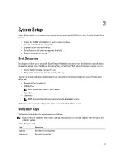
...to a specific device (for example: optical drive or hard drive). During the Power-on Self Test (POST), when the Dell logo appears, you can: • Access System Setup by pressing key • Bring up the one-time boot menu by pressing key The one-time boot menu displays the devices that ...option. NOTE: For most of the system setup options, changes that you can : • Change the NVRAM settings after you add or remove hardware • View the system hardware configuration • Enable or disable integrated devices • Set performance and power management thresholds • Manage...
...to a specific device (for example: optical drive or hard drive). During the Power-on Self Test (POST), when the Dell logo appears, you can: • Access System Setup by pressing key • Bring up the one-time boot menu by pressing key The one-time boot menu displays the devices that ...option. NOTE: For most of the system setup options, changes that you can : • Change the NVRAM settings after you add or remove hardware • View the system hardware configuration • Enable or disable integrated devices • Set performance and power management thresholds • Manage...


