
User Guide
Page 1
... 1999 Last revised: 17 Jan 2001 Dell Computer Corporation disclaims any manner whatsoever without notice. © 2000-2001 Dell Computer Corporation. Dell™ OptiPlex™ GX100 System User's Guide Introduction Setup and Operation System Setup Installing Upgrades Troubleshooting Technical Specifications NOTE:... Machines Corporation; Reproduction in any proprietary interest in this text: Dell, OptiPlex, OptiFrame, Dell OpenManage, Dimension, Latitude, Inspiron, and DellWare are registered trademarks of Dell Computer Corporation is subject to hardware or loss of data and tells...
... 1999 Last revised: 17 Jan 2001 Dell Computer Corporation disclaims any manner whatsoever without notice. © 2000-2001 Dell Computer Corporation. Dell™ OptiPlex™ GX100 System User's Guide Introduction Setup and Operation System Setup Installing Upgrades Troubleshooting Technical Specifications NOTE:... Machines Corporation; Reproduction in any proprietary interest in this text: Dell, OptiPlex, OptiFrame, Dell OpenManage, Dimension, Latitude, Inspiron, and DellWare are registered trademarks of Dell Computer Corporation is subject to hardware or loss of data and tells...
User Guide
Page 2
...source of your system displayed a message or emitted a beep code, see the documentation that came with the procedures in System Setup. l Run the Dell Diagnostics. Basic Checks See the following steps in the order indicated until the problem is resolved: l If your computer is faulty... see "Getting Help." Back to Contents Page Basic Checks: Dell™ OptiPlex™ GX100 System User's Guide Overview Checking Connections and Switches Backing Up Your Files Look and Listen Basic Checks System Setup Overview If your Dell computer system is not working as expected, and if you to...
...source of your system displayed a message or emitted a beep code, see the documentation that came with the procedures in System Setup. l Run the Dell Diagnostics. Basic Checks See the following steps in the order indicated until the problem is resolved: l If your computer is faulty... see "Getting Help." Back to Contents Page Basic Checks: Dell™ OptiPlex™ GX100 System User's Guide Overview Checking Connections and Switches Backing Up Your Files Look and Listen Basic Checks System Setup Overview If your Dell computer system is not working as expected, and if you to...
User Guide
Page 3
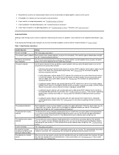
... you identify a system problem when you can test the drive by opening Windows Explorer and clicking the icon for instructions on getting technical assistance from Dell. The power indicator Use the power indicator to your monitor is important in determining the source of a problem. l A solid yellow power indicator...diskette drive. If your mouse or printer is properly seated, remove all DIMMs, install only one or more indicators (usually in "System Setup." The power and hard-disk drive indicators Use the power and hard-disk drive indicators to access the boot files from...
... you identify a system problem when you can test the drive by opening Windows Explorer and clicking the icon for instructions on getting technical assistance from Dell. The power indicator Use the power indicator to your monitor is important in determining the source of a problem. l A solid yellow power indicator...diskette drive. If your mouse or printer is properly seated, remove all DIMMs, install only one or more indicators (usually in "System Setup." The power and hard-disk drive indicators Use the power and hard-disk drive indicators to access the boot files from...

User Guide
Page 4
... recorded by verifying the correct settings in System Setup you boot your system, your system's hardware configuration and forgot to Contents Page To correct this problem, enter System Setup, correct the setting for the corresponding System Setup program option, and reboot your screen. This ...problem can easily correct certain system problems by System Setup, an error message may appear on your system. Back to run System Setup. When you have not resolved the problem, see "Dell Diagnostics." System Setup You can happen if you changed your system checks the system...
... recorded by verifying the correct settings in System Setup you boot your system, your system's hardware configuration and forgot to Contents Page To correct this problem, enter System Setup, correct the setting for the corresponding System Setup program option, and reboot your screen. This ...problem can easily correct certain system problems by System Setup, an error message may appear on your system. Back to run System Setup. When you have not resolved the problem, see "Dell Diagnostics." System Setup You can happen if you changed your system checks the system...
User Guide
Page 5
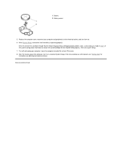
...Dell™ OptiPlex™ GX100 System User's Guide Overview Replacing the Battery Overview A 3.0-volt (V) CR2032 coin-cell battery installed on the system board maintains system configuration, date, and time information in a special section of the battery. please run SETUP program or Invalid configuration information please run SETUP...circuit traces on your battery. Pry the battery out of the system configuration information to the instructions in System Setup, replace your system. Install the new battery. Remove the computer cover according to restore the correct settings. ...
...Dell™ OptiPlex™ GX100 System User's Guide Overview Replacing the Battery Overview A 3.0-volt (V) CR2032 coin-cell battery installed on the system board maintains system configuration, date, and time information in a special section of the battery. please run SETUP program or Invalid configuration information please run SETUP...circuit traces on your battery. Pry the battery out of the system configuration information to the instructions in System Setup, replace your system. Install the new battery. Remove the computer cover according to restore the correct settings. ...
User Guide
Page 6
... outlets, and turn it on obtaining technical assistance. If the time and date are still incorrect, see "Getting Help" for instructions on , and enter System Setup. Also, use the copy you made in the computer, turn them on. 6. Turn off for other System... Setup options. Back to Contents Page Enter the correct time and date through System Setup's System Time and System Date options. Enter System Setup, and confirm that the battery is operating properly. Leave the computer turned off and unplug...
... outlets, and turn it on obtaining technical assistance. If the time and date are still incorrect, see "Getting Help" for instructions on , and enter System Setup. Also, use the copy you made in the computer, turn them on. 6. Turn off for other System... Setup options. Back to Contents Page Enter the correct time and date through System Setup's System Time and System Date options. Enter System Setup, and confirm that the battery is operating properly. Leave the computer turned off and unplug...

User Guide
Page 16
... Dell™ Diagnostics: Dell OptiPlex™ GX100 System User's Guide Overview Features Before You Start Testing Starting the Dell Diagnostics Advanced Testing Overview If you experience a problem with other computers may cause incorrect computer responses or result in error messages. NOTICE: Only use the Dell ...Diagnostics to test your printer if one or all of the boot routine to access the System Setup screen. 3. l Enter system setup, confirm your computer's system configuration information, and enable all devices...
... Dell™ Diagnostics: Dell OptiPlex™ GX100 System User's Guide Overview Features Before You Start Testing Starting the Dell Diagnostics Advanced Testing Overview If you experience a problem with other computers may cause incorrect computer responses or result in error messages. NOTICE: Only use the Dell ...Diagnostics to test your printer if one or all of the boot routine to access the System Setup screen. 3. l Enter system setup, confirm your computer's system configuration information, and enable all devices...
User Guide
Page 17
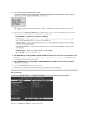
...One Device, press for a thorough check of your computer or to fit your needs, and restart your test(s). 11. Press to exit system setup and save the change the boot sequence, repeat steps 1 through 6, set the boot sequence to check a particular area of locating the problem quickly.... 9. After you to customize your computer. 7. Exits to MS-DOS - The computer reboots and the Dell logo screen appears, followed by pressing the up- Select Quick Tests from the Diagnostics Main Menu screen, the following Diagnostics Main Menu screen appears...
...One Device, press for a thorough check of your computer or to fit your needs, and restart your test(s). 11. Press to exit system setup and save the change the boot sequence, repeat steps 1 through 6, set the boot sequence to check a particular area of locating the problem quickly.... 9. After you to customize your computer. 7. Exits to MS-DOS - The computer reboots and the Dell logo screen appears, followed by pressing the up- Select Quick Tests from the Diagnostics Main Menu screen, the following Diagnostics Main Menu screen appears...
User Guide
Page 22
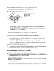
...10. Connect the appropriate interface cable to Not Installed. Otherwise, use the spare connector on . 13. l For a diskette drive, enter System Setup and update the appropriate Diskette Drive A or Diskette Drive B option to verify that came with its own controller card, connect the other end ...of drive. NOTE: Tape drives sold by running the Dell Diagnostics. Unpack the drive and prepare it for your system configuration information. l If you install a drive, see Figure 7 in "Inside ...
...10. Connect the appropriate interface cable to Not Installed. Otherwise, use the spare connector on . 13. l For a diskette drive, enter System Setup and update the appropriate Diskette Drive A or Diskette Drive B option to verify that came with its own controller card, connect the other end ...of drive. NOTE: Tape drives sold by running the Dell Diagnostics. Unpack the drive and prepare it for your system configuration information. l If you install a drive, see Figure 7 in "Inside ...
User Guide
Page 24
... out of the drive (see Figure 12). If your new diskette drive. Connect the appropriate interface cable to your system works correctly by running the Dell Diagnostics. l For a diskette drive, update the appropriate Diskette Drive option (A or B) to reflect the size and capacity of the interface cable to the interface... possible damage to the interface connector on the cable with an EIDE CD-ROM or tape drive, use the EIDE interface cable provided in System Setup. l For an EIDE tape drive or CD-ROM drive, connect the other end of your system came with pin 1 on the system board (see...
... out of the drive (see Figure 12). If your new diskette drive. Connect the appropriate interface cable to your system works correctly by running the Dell Diagnostics. l For a diskette drive, update the appropriate Diskette Drive option (A or B) to reflect the size and capacity of the interface cable to the interface... possible damage to the interface connector on the cable with an EIDE CD-ROM or tape drive, use the EIDE interface cable provided in System Setup. l For an EIDE tape drive or CD-ROM drive, connect the other end of your system came with pin 1 on the system board (see...
User Guide
Page 29
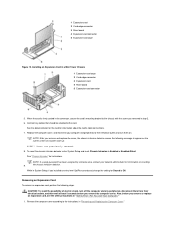
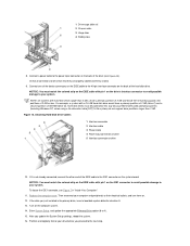
... other precautions in the connector, secure the card's mounting bracket to the chassis with the screw you installed an entry-level OptiPlex sound card, change the setting for information on . See the documentation for the card for instructions. To reset the chassis intrusion ... 3 Expansion card 4 Riser board 5 Expansion-card connector 5. See "Chassis Intrusion" for information about the card's cable connections. 7. NOTE: If a setup password has been assigned by someone else, contact your computer and peripherals to their electrical outlets, and then wait at the next system start-up...
... other precautions in the connector, secure the card's mounting bracket to the chassis with the screw you installed an entry-level OptiPlex sound card, change the setting for information on . See the documentation for the card for instructions. To reset the chassis intrusion ... 3 Expansion card 4 Riser board 5 Expansion-card connector 5. See "Chassis Intrusion" for information about the card's cable connections. 7. NOTE: If a setup password has been assigned by someone else, contact your computer and peripherals to their electrical outlets, and then wait at the next system start-up...

User Guide
Page 30
... a metal filler bracket over empty card-slot openings to appear on . the chassis intrusion detector. 2. If you want to Enabled or Enabled-Silent. NOTE: If a setup password has been assigned by its connector. 5. To reset the chassis intrusion detector, enter System...
... a metal filler bracket over empty card-slot openings to appear on . the chassis intrusion detector. 2. If you want to Enabled or Enabled-Silent. NOTE: If a setup password has been assigned by its connector. 5. To reset the chassis intrusion detector, enter System...
User Guide
Page 32
...I/O port and the peripheral device l A faulty cable between the I/O port and the peripheral device l A faulty peripheral device l Incorrect settings in System Setup l Incorrect settings in your computer's I /O Device," depending on obtaining technical assistance. You can be tested as instructed in the system's configuration files ... parallel printer, perform the following steps in the order indicated until the problem is resolved: 1. Start the Dell Diagnostics by inserting the Dell ResourceCD into the CD-ROM drive and rebooting the system. 4. If the Mouse Test fails, the system ...
...I/O port and the peripheral device l A faulty cable between the I/O port and the peripheral device l A faulty peripheral device l Incorrect settings in System Setup l Incorrect settings in your computer's I /O Device," depending on obtaining technical assistance. You can be tested as instructed in the system's configuration files ... parallel printer, perform the following steps in the order indicated until the problem is resolved: 1. Start the Dell Diagnostics by inserting the Dell ResourceCD into the CD-ROM drive and rebooting the system. 4. If the Mouse Test fails, the system ...
User Guide
Page 37
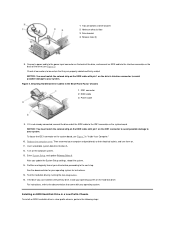
... interface connector on the hard-disk drive. To locate the IDE1 connector on the computer system. 13. Enter System Setup, and update Primary Drive 0. If the drive you update the System Setup settings, reboot the system. 14. Installing an EIDE Hard-Disk Drive in a Low-Profile Chassis To install an...an EIDE cable to the IDE1 connector on . 11. Turn on the system board, see Figure 5). Test the hard-disk drive by running the Dell Diagnostics. 16. For instructions, refer to be certain that came with your system. Check all connectors to the documentation that they are properly cabled ...
... interface connector on the hard-disk drive. To locate the IDE1 connector on the computer system. 13. Enter System Setup, and update Primary Drive 0. If the drive you update the System Setup settings, reboot the system. 14. Installing an EIDE Hard-Disk Drive in a Low-Profile Chassis To install an...an EIDE cable to the IDE1 connector on . 11. Turn on the system board, see Figure 5). Test the hard-disk drive by running the Dell Diagnostics. 16. For instructions, refer to be certain that came with your system. Check all connectors to the documentation that they are properly cabled ...
User Guide
Page 39
... system. After you just installed is the primary drive, install your system. If the drive you update the System Setup settings, reboot the system. 16. Enter System Setup, and update the appropriate Primary Drive option (0 or 1). 15. For You and Your Computer." 1. b. Then ...before you continue this procedure. 2. NOTICE: To avoid possibly damaging the drive by electromagnetic static (EMS), ground yourself by running the Dell Diagnostics. 18. Slide the bracket into drive A. 13. Partition and logically format your files before you just installed is not already ...
... system. After you just installed is the primary drive, install your system. If the drive you update the System Setup settings, reboot the system. 16. Enter System Setup, and update the appropriate Primary Drive option (0 or 1). 15. For You and Your Computer." 1. b. Then ...before you continue this procedure. 2. NOTICE: To avoid possibly damaging the drive by electromagnetic static (EMS), ground yourself by running the Dell Diagnostics. 18. Slide the bracket into drive A. 13. Partition and logically format your files before you just installed is not already ...
User Guide
Page 41
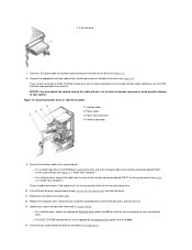
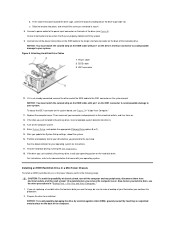
... the IDE1 connector, see Figure 12). Then reconnect your drive before you proceed to the power input connector on drive 10. Enter System Setup, and update the appropriate Primary Drive option (0 or 1). 15. Partition and logically format your computer and peripherals to their electrical outlets, and...drives larger than 2 GB. 1 Drive-cage slide rail 2 Chassis slots 3 Hinge tabs 4 Sliding tabs 8. If the drive you update the System Setup settings, reboot the system. 16. Replace the computer cover. Turn on the system board. NOTICE: You must be certain that they are properly cabled...
... the IDE1 connector, see Figure 12). Then reconnect your drive before you proceed to the power input connector on drive 10. Enter System Setup, and update the appropriate Primary Drive option (0 or 1). 15. Partition and logically format your computer and peripherals to their electrical outlets, and...drives larger than 2 GB. 1 Drive-cage slide rail 2 Chassis slots 3 Hinge tabs 4 Sliding tabs 8. If the drive you update the System Setup settings, reboot the system. 16. Replace the computer cover. Turn on the system board. NOTICE: You must be certain that they are properly cabled...
User Guide
Page 57
.... Disconnect the computer and peripherals from the computer. Back to Contents Page Internal Components: Dell™ OptiPlex™ GX100 System User's Guide Overview Troubleshooting Expansion Cards Safety First-For You and Your Computer Troubleshooting System Memory Removing and ..., perform the following steps: 1. To remove the computer cover, perform the following steps in "Checking Connections and Switches" and "System Setup." Doing so reduces the potential for your small form-factor or low-profile chassis has an optional stand attached to service the computer except...
.... Disconnect the computer and peripherals from the computer. Back to Contents Page Internal Components: Dell™ OptiPlex™ GX100 System User's Guide Overview Troubleshooting Expansion Cards Safety First-For You and Your Computer Troubleshooting System Memory Removing and ..., perform the following steps: 1. To remove the computer cover, perform the following steps in "Checking Connections and Switches" and "System Setup." Doing so reduces the potential for your small form-factor or low-profile chassis has an optional stand attached to service the computer except...
User Guide
Page 61
... Also, disconnect any telephone or telecommunication lines from the computer. Replace the battery only with the battery or if System Setup loses the system configuration information when the computer is turned off the system, including any telephone or telecommunication lines to see...: There is not resolved, replace the battery. To troubleshoot the battery, perform the following steps: 1. Start the Dell Diagnostics by inserting the Dell ResourceCD and rebooting the system. 9. Verify the diskette/tape drive, hard-disk drive, and all the expansion-card connections...
... Also, disconnect any telephone or telecommunication lines from the computer. Replace the battery only with the battery or if System Setup loses the system configuration information when the computer is turned off the system, including any telephone or telecommunication lines to see...: There is not resolved, replace the battery. To troubleshoot the battery, perform the following steps: 1. Start the Dell Diagnostics by inserting the Dell ResourceCD and rebooting the system. 9. Verify the diskette/tape drive, hard-disk drive, and all the expansion-card connections...
User Guide
Page 62
... from the electrical outlet, and remove the computer cover. 10. If an error message indicates invalid system configuration information, enter System Setup and check the System Memory option. If the problem is firmly seated in -line memory module (DIMM) or a faulty system board...system, disconnect it should flash momentarily and then turn it from the computer. Turn on . 4. Verify that DIMM. Start the Dell Diagnostics by inserting the Dell ResourceCD and rebooting the system. 5. CAUTION: Before you turn off . Troubleshooting the Video Subsystem If the tests complete successfully, ...
... from the electrical outlet, and remove the computer cover. 10. If an error message indicates invalid system configuration information, enter System Setup and check the System Memory option. If the problem is firmly seated in -line memory module (DIMM) or a faulty system board...system, disconnect it should flash momentarily and then turn it from the computer. Turn on . 4. Verify that DIMM. Start the Dell Diagnostics by inserting the Dell ResourceCD and rebooting the system. 5. CAUTION: Before you turn off . Troubleshooting the Video Subsystem If the tests complete successfully, ...
User Guide
Page 63
... from the computer. Verify that the DC power cables from the power supply are firmly connected to the system board. Enter System Setup, and verify that the interface cable for each drive. Also verify that the problem drive is firmly connected to the drive and ...for instructions on obtaining technical assistance. If an error message indicates a system board problem, perform the following steps: 1. Start the Dell Diagnostics by inserting the Dell ResourceCD and rebooting the system. 2. Run the appropriate test group for instructions on the system board. 6. If the monitor is ...
... from the computer. Verify that the DC power cables from the power supply are firmly connected to the system board. Enter System Setup, and verify that the interface cable for each drive. Also verify that the problem drive is firmly connected to the drive and ...for instructions on obtaining technical assistance. If an error message indicates a system board problem, perform the following steps: 1. Start the Dell Diagnostics by inserting the Dell ResourceCD and rebooting the system. 2. Run the appropriate test group for instructions on the system board. 6. If the monitor is ...


