
Dell OptiPlex 9030 All-In-One Owners Manual
Page 1
Dell OptiPlex 9030 All-In-One Owner's Manual Regulatory Model: W09C Regulatory Type: W09C001
Dell OptiPlex 9030 All-In-One Owner's Manual Regulatory Model: W09C Regulatory Type: W09C001

Dell OptiPlex 9030 All-In-One Owners Manual
Page 2
CAUTION: A CAUTION indicates either potential damage to avoid the problem. Copyright © 2014 Dell Inc. Dell™ and the Dell logo are trademarks of their respective companies. 2014 - 06 Rev. All rights reserved. This product is protected by U.S. All other jurisdictions. A00 WARNING: A WARNING indicates a ... and tells you make better use of your computer. in the United States and/or other marks and names mentioned herein may be trademarks of Dell Inc.
CAUTION: A CAUTION indicates either potential damage to avoid the problem. Copyright © 2014 Dell Inc. Dell™ and the Dell logo are trademarks of their respective companies. 2014 - 06 Rev. All rights reserved. This product is protected by U.S. All other jurisdictions. A00 WARNING: A WARNING indicates a ... and tells you make better use of your computer. in the United States and/or other marks and names mentioned herein may be trademarks of Dell Inc.

Dell OptiPlex 9030 All-In-One Owners Manual
Page 3
Contents 1 Working on Your Computer 5 Before Working Inside Your Computer 5 Recommended Tools...6 Turning Off Your Computer...7 After Working Inside Your Computer 7 Important Information...8 2 Removing and Installing Components 9 System Overview...9 Removing the VESA Stand...10 Installing the VESA Stand...11 Removing the Back Cover...11 Installing the Back Cover...12 Removing the Memory...12 Installing the Memory...13 Removing the VESA Mount Bracket...13 Installing the VESA Mount Bracket...14 Removing the Power and On-Screen Display (OSD) Buttons Board 14 Installing the Power and OSD ...
Contents 1 Working on Your Computer 5 Before Working Inside Your Computer 5 Recommended Tools...6 Turning Off Your Computer...7 After Working Inside Your Computer 7 Important Information...8 2 Removing and Installing Components 9 System Overview...9 Removing the VESA Stand...10 Installing the VESA Stand...11 Removing the Back Cover...11 Installing the Back Cover...12 Removing the Memory...12 Installing the Memory...13 Removing the VESA Mount Bracket...13 Installing the VESA Mount Bracket...14 Removing the Power and On-Screen Display (OSD) Buttons Board 14 Installing the Power and OSD ...

Dell OptiPlex 9030 All-In-One Owners Manual
Page 4
... Setup Password...54 Assigning a System Password and Setup Password 54 Deleting or Changing an Existing System and/or Setup Password 55 4 Technical Specifications 56 5 Contacting Dell...61
... Setup Password...54 Assigning a System Password and Setup Password 54 Deleting or Changing an Existing System and/or Setup Password 55 4 Technical Specifications 56 5 Contacting Dell...61
Dell OptiPlex 9030 All-In-One Owners Manual
Page 5
... on the locking tabs before you are correctly oriented and aligned. if you connect a cable, ensure that is not authorized by Dell is not covered by performing the removal procedure in this document. 5 Also, before you disconnect a cable, pull on its connector... this document assumes that shipped with locking tabs; For additional safety best practices information, see the Regulatory Compliance Homepage at www.dell.com/regulatory_compliance CAUTION: Many repairs may appear differently than shown in reverse order. CAUTION: Handle components and cards with your computer...
... on the locking tabs before you are correctly oriented and aligned. if you connect a cable, ensure that is not authorized by Dell is not covered by performing the removal procedure in this document. 5 Also, before you disconnect a cable, pull on its connector... this document assumes that shipped with locking tabs; For additional safety best practices information, see the Regulatory Compliance Homepage at www.dell.com/regulatory_compliance CAUTION: Many repairs may appear differently than shown in reverse order. CAUTION: Handle components and cards with your computer...

Dell OptiPlex 9030 All-In-One Owners Manual
Page 6
CAUTION: To disconnect a network cable, first unplug the cable from your computer and then unplug the cable from being scratched. 2. Press and hold the power button while the computer is flat and clean to prevent the computer cover from the network device. 3. Disconnect all attached devices from the computer. 4. Disconnect your computer and all network cables from their electrical outlets. 5. To avoid damaging your computer, perform the following tools: • Small flat-blade screwdriver • Phillips screwdriver • Small plastic scribe 6 Remove the cover. CAUTION: ...
CAUTION: To disconnect a network cable, first unplug the cable from your computer and then unplug the cable from being scratched. 2. Press and hold the power button while the computer is flat and clean to prevent the computer cover from the network device. 3. Disconnect all attached devices from the computer. 4. Disconnect your computer and all network cables from their electrical outlets. 5. To avoid damaging your computer, perform the following tools: • Small flat-blade screwdriver • Phillips screwdriver • Small plastic scribe 6 Remove the cover. CAUTION: ...

Dell OptiPlex 9030 All-In-One Owners Manual
Page 7
... down . Select the - Using a mouse: and then select Shut down the operating system: • In Windows 8.1: - Ensure that the computer works correctly by running the Dell Diagnostics. 7 After Working Inside Your Computer After you complete any replacement procedure, ensure you connect any telephone or network cables to upper-right corner of...
... down . Select the - Using a mouse: and then select Shut down the operating system: • In Windows 8.1: - Ensure that the computer works correctly by running the Dell Diagnostics. 7 After Working Inside Your Computer After you complete any replacement procedure, ensure you connect any telephone or network cables to upper-right corner of...

Dell OptiPlex 9030 All-In-One Owners Manual
Page 8
Important Information NOTE: Avoid using the touchscreen in temperature may cause condensation on the inner surface of the glass screen, which will disappear after a short time and does not affect normal usage. 8 NOTE: Sudden change in dusty, hot, or humid environments.
Important Information NOTE: Avoid using the touchscreen in temperature may cause condensation on the inner surface of the glass screen, which will disappear after a short time and does not affect normal usage. 8 NOTE: Sudden change in dusty, hot, or humid environments.

Dell OptiPlex 9030 All-In-One Owners Manual
Page 9
2 Removing and Installing Components This section provides detailed information on -screen display (OSD) buttons board 9. Inside View - 1 1. optical drive 11. memory shield 3. intrusion switch 10. power-supply fan bracket 12. power-supply unit 13. power-supply diagnostic board 6. VESA mount bracket 9 System Overview Figure 1. power-supply fan 7. converter board 8. speaker cover 5. system board shield 2. I/O board shield 4. power and on how to remove or install the components from your computer.
2 Removing and Installing Components This section provides detailed information on -screen display (OSD) buttons board 9. Inside View - 1 1. optical drive 11. memory shield 3. intrusion switch 10. power-supply fan bracket 12. power-supply unit 13. power-supply diagnostic board 6. VESA mount bracket 9 System Overview Figure 1. power-supply fan 7. converter board 8. speaker cover 5. system board shield 2. I/O board shield 4. power and on how to remove or install the components from your computer.
Dell OptiPlex 9030 All-In-One Owners Manual
Page 10
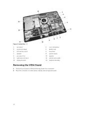
processor 3. speaker 9. hard drive 8. Follow the procedures in Before Working Inside Your Computer. 2. processor fan 11. speaker 12. left side lock latch 7. WLAN card 6. optical-drive cable 14. Figure 2. Inside View - 2 1. display bracket 2. system board 10. memory module 5. coin-cell battery 4. Place the computer on a flat surface, display side facing downwards. 10 right side lock latch 13. heatsink assembly Removing the VESA Stand 1.
processor 3. speaker 9. hard drive 8. Follow the procedures in Before Working Inside Your Computer. 2. processor fan 11. speaker 12. left side lock latch 7. WLAN card 6. optical-drive cable 14. Figure 2. Inside View - 2 1. display bracket 2. system board 10. memory module 5. coin-cell battery 4. Place the computer on a flat surface, display side facing downwards. 10 right side lock latch 13. heatsink assembly Removing the VESA Stand 1.

Dell OptiPlex 9030 All-In-One Owners Manual
Page 11
Follow the procedures in After Working Inside Your Computer. Lift the VESA stand upwards and away from the back cover. Place and press the VESA cover on the VESA cover to release the stand. 4. Press the button on the computer, until it clicks into place. 3. Align and place the VESA stand on the back of the computer. 2. Removing the Back Cover 1. Remove the VESA stand. 11 3. Installing the VESA Stand 1. Follow the procedures in Before Working Inside Your Computer. 2.
Follow the procedures in After Working Inside Your Computer. Lift the VESA stand upwards and away from the back cover. Place and press the VESA cover on the VESA cover to release the stand. 4. Press the button on the computer, until it clicks into place. 3. Align and place the VESA stand on the back of the computer. 2. Removing the Back Cover 1. Remove the VESA stand. 11 3. Installing the VESA Stand 1. Follow the procedures in Before Working Inside Your Computer. 2.

Dell OptiPlex 9030 All-In-One Owners Manual
Page 12
Hold locks on both sides to secure the back cover to its original position on two sides that secure the back cover to the computer. Follow the procedures in After Working Inside Your Computer. VESA stand b. 3. Lift the back cover upwards and remove it from the computer. Install the VESA stand. 4. Remove the: a. Removing the Memory 1. back cover 12 Align the back cover to the computer. 3. Follow the procedures in Before Working Inside Your Computer. 2. Release the latches on the computer. 2. Installing the Back Cover 1.
Hold locks on both sides to secure the back cover to its original position on two sides that secure the back cover to the computer. Follow the procedures in After Working Inside Your Computer. VESA stand b. 3. Lift the back cover upwards and remove it from the computer. Install the VESA stand. 4. Remove the: a. Removing the Memory 1. back cover 12 Align the back cover to the computer. 3. Follow the procedures in Before Working Inside Your Computer. 2. Release the latches on the computer. 2. Installing the Back Cover 1.

Dell OptiPlex 9030 All-In-One Owners Manual
Page 13
Pry the retention clips away from its place. 4. Lift and remove the memory module from the memory module until the release tabs spring back to secure them in the system-board connector. 2. Place the memory shield back into its connector. Remove the: a. Align the notch on the memory module until it pops-up. VESA stand 5. Follow the procedures in Before Working Inside Your Computer. 2. Follow the procedures in After Working Inside Your Computer. 3. Press down on the memory-card with the tab in place. 3. Removing the VESA Mount Bracket 1. back cover 13 Install ...
Pry the retention clips away from its place. 4. Lift and remove the memory module from the memory module until the release tabs spring back to secure them in the system-board connector. 2. Place the memory shield back into its connector. Remove the: a. Align the notch on the memory module until it pops-up. VESA stand 5. Follow the procedures in Before Working Inside Your Computer. 2. Follow the procedures in After Working Inside Your Computer. 3. Press down on the memory-card with the tab in place. 3. Removing the VESA Mount Bracket 1. back cover 13 Install ...

Dell OptiPlex 9030 All-In-One Owners Manual
Page 14
Installing the VESA Mount Bracket 1. Tighten the screws that secure the VESA mount bracket to the computer. 3. Removing the Power and On-Screen Display (OSD) Buttons Board 1. Follow the procedures in Before Working Inside Your Computer. 2. VESA stand b. Remove the screws that secure the VESA mount bracket to the computer. Lift the bracket away from the computer. Install the: a. Remove the: a. Align and place the bracket on the back of the computer. 2. back cover b. back cover 14 VESA stand 4. Follow the procedures in After Working Inside Your Computer. 3.
Installing the VESA Mount Bracket 1. Tighten the screws that secure the VESA mount bracket to the computer. 3. Removing the Power and On-Screen Display (OSD) Buttons Board 1. Follow the procedures in Before Working Inside Your Computer. 2. VESA stand b. Remove the screws that secure the VESA mount bracket to the computer. Lift the bracket away from the computer. Install the: a. Remove the: a. Align and place the bracket on the back of the computer. 2. back cover b. back cover 14 VESA stand 4. Follow the procedures in After Working Inside Your Computer. 3.

Dell OptiPlex 9030 All-In-One Owners Manual
Page 15
Perform the following steps as shown in After Working Inside Your Computer. Lift the power and OSD buttons board from the computer [3]. VESA stand 4. Remove the tape that secures the power and OSD buttons board to the power and OSD buttons board. 3. b. Disconnect the cable from the power and OSD buttons board to secure it from the chassis [2]. Installing the Power and OSD Buttons Board 1. Follow the procedures in the illustration: a. Remove the: a. back cover b. Removing the System-Board Shield 1. Install: a. VESA stand b. 3. c. Insert the power and OSD ...
Perform the following steps as shown in After Working Inside Your Computer. Lift the power and OSD buttons board from the computer [3]. VESA stand 4. Remove the tape that secures the power and OSD buttons board to the power and OSD buttons board. 3. b. Disconnect the cable from the power and OSD buttons board to secure it from the chassis [2]. Installing the Power and OSD Buttons Board 1. Follow the procedures in the illustration: a. Remove the: a. back cover b. Removing the System-Board Shield 1. Install: a. VESA stand b. 3. c. Insert the power and OSD ...

Dell OptiPlex 9030 All-In-One Owners Manual
Page 16
Press the securing tab down to the computer. 3. VESA stand 4. Removing the Converter Board 1. Slide the system-board shield and lift it away from the slots on the back of the computer. 2. Installing the System-Board Shield 1. Install the: a. back cover c. VESA stand b. Tighten the screws that secure the system-board shield to release the system-board shield from the computer [2]. Remove the: a. b. Align and place the system-board shield on the chassis [1]. Follow the procedures in the illustration: a. VESA mount bracket b. Perform the following steps as shown...
Press the securing tab down to the computer. 3. VESA stand 4. Removing the Converter Board 1. Slide the system-board shield and lift it away from the slots on the back of the computer. 2. Installing the System-Board Shield 1. Install the: a. back cover c. VESA stand b. Tighten the screws that secure the system-board shield to release the system-board shield from the computer [2]. Remove the: a. b. Align and place the system-board shield on the chassis [1]. Follow the procedures in the illustration: a. VESA mount bracket b. Perform the following steps as shown...

Dell OptiPlex 9030 All-In-One Owners Manual
Page 17
b. Tighten the screws to secure the converter board to the connectors on the converter board. 4. Follow the procedures in the illustration: a. Perform the following steps as shown in After Working Inside Your Computer. 17 d. VESA stand 5. Disconnect the converter-board cable from the computer [4]. Connect the converter-board cable and display-backlight cable to the computer. 3. Lift the converter board away from the connectors on the converter board [1]. Install the: a. c. Place the convertor board into its place. 2. Disconnect the cables from the ...
b. Tighten the screws to secure the converter board to the connectors on the converter board. 4. Follow the procedures in the illustration: a. Perform the following steps as shown in After Working Inside Your Computer. 17 d. VESA stand 5. Disconnect the converter-board cable from the computer [4]. Connect the converter-board cable and display-backlight cable to the computer. 3. Lift the converter board away from the connectors on the converter board [1]. Install the: a. c. Place the convertor board into its place. 2. Disconnect the cables from the ...

Dell OptiPlex 9030 All-In-One Owners Manual
Page 18
VESA stand b. Press the release latch away from the socket; Installing the Coin-Cell Battery 1. Removing the Optical Drive 1. back cover 18 Follow the procedures in Before Working Inside Your Computer. 2. system-board shield 3. The battery pops-out from the battery. system-board shield b. Install: a. base cover c. back cover c. lift the coin-cell battery out of the computer. Press the coin-cell battery downward until the release latch springs back into its slot on the system board. 2. VESA stand b. VESA stand 4. Removing the Coin-Cell Battery 1. ...
VESA stand b. Press the release latch away from the socket; Installing the Coin-Cell Battery 1. Removing the Optical Drive 1. back cover 18 Follow the procedures in Before Working Inside Your Computer. 2. system-board shield 3. The battery pops-out from the battery. system-board shield b. Install: a. base cover c. back cover c. lift the coin-cell battery out of the computer. Press the coin-cell battery downward until the release latch springs back into its slot on the system board. 2. VESA stand b. VESA stand 4. Removing the Coin-Cell Battery 1. ...

Dell OptiPlex 9030 All-In-One Owners Manual
Page 19
Press the securing tab down to remove it from the computer [2]. 4. Slide the optical drive outward to release the optical drive [1]. Unthread the cable from the connector on the system board [1] [2]. b. Disconnect the optical-drive cables from the notches of the computer [3]. 19 3. b. Perform the following steps as shown in the illustration: a. Perform the following steps as shown in the illustration: a.
Press the securing tab down to remove it from the computer [2]. 4. Slide the optical drive outward to release the optical drive [1]. Unthread the cable from the connector on the system board [1] [2]. b. Disconnect the optical-drive cables from the notches of the computer [3]. 19 3. b. Perform the following steps as shown in the illustration: a. Perform the following steps as shown in the illustration: a.

Dell OptiPlex 9030 All-In-One Owners Manual
Page 20
Connect the optical-drive cable. 3. VESA stand b. Disconnect the hard-drive cables from the notches. Remove the screws that secure the optical-drive cable to the computer. 4. VESA stand 5. Remove the: a. VESA mount bracket 3. Removing the Hard Drive 1. Follow the procedures in After Working Inside Your Computer. back cover c. Unthread the cables from the notches on the hard-drive bracket. back cover b. Lock and secure the optical drive to the system and unthread the cables from the hard drive. 20 Installing the Optical Drive 1. Install the: a. Align and slide...
Connect the optical-drive cable. 3. VESA stand b. Disconnect the hard-drive cables from the notches. Remove the screws that secure the optical-drive cable to the computer. 4. VESA stand 5. Remove the: a. VESA mount bracket 3. Removing the Hard Drive 1. Follow the procedures in After Working Inside Your Computer. back cover c. Unthread the cables from the notches on the hard-drive bracket. back cover b. Lock and secure the optical drive to the system and unthread the cables from the hard drive. 20 Installing the Optical Drive 1. Install the: a. Align and slide...