
Owner's Manual
Page 3
... Memory...12 Installing the Memory...13 Removing the VESA Mount Bracket...13 Installing the VESA Mount Bracket...14 Removing the Power and On-Screen Display (OSD) Buttons Board 14 Installing the Power and On-Screen Display (OSD) Buttons Board 15 Removing the System-Board Shield...15 Installing the System-Board Shield...16......23 Removing the Heat-Sink Assembly...23 Installing the Heat-Sink Assembly...23 Removing the Processor Fan...24 Installing the Processor Fan...24 Removing the Power-Supply Fan...24 Installing the Power-Supply Fan...25
... Memory...12 Installing the Memory...13 Removing the VESA Mount Bracket...13 Installing the VESA Mount Bracket...14 Removing the Power and On-Screen Display (OSD) Buttons Board 14 Installing the Power and On-Screen Display (OSD) Buttons Board 15 Removing the System-Board Shield...15 Installing the System-Board Shield...16......23 Removing the Heat-Sink Assembly...23 Installing the Heat-Sink Assembly...23 Removing the Processor Fan...24 Installing the Processor Fan...24 Removing the Power-Supply Fan...24 Installing the Power-Supply Fan...25

Owner's Manual
Page 4
Removing the I/O Board Shield...26 Installing the I/O Board Shield...28 Removing the Power Supply Unit (PSU)...28 Installing the Power Supply Unit...29 Removing the Processor...30 Installing the Processor...30 Removing the Speakers...30 Installing the Speakers...31 Removing the System Board...32 System Board ... Setup Password...53 Assigning a System Password and Setup Password 54 Deleting or Changing an Existing System and/or Setup Password 54 4 Technical Specifications...57 5 Contacting Dell...63
Removing the I/O Board Shield...26 Installing the I/O Board Shield...28 Removing the Power Supply Unit (PSU)...28 Installing the Power Supply Unit...29 Removing the Processor...30 Installing the Processor...30 Removing the Speakers...30 Installing the Speakers...31 Removing the System Board...32 System Board ... Setup Password...53 Assigning a System Password and Setup Password 54 Deleting or Changing an Existing System and/or Setup Password 54 4 Technical Specifications...57 5 Contacting Dell...63

Owner's Manual
Page 9
2 Removing and Installing Components This section provides detailed information on how to remove or install the components from your computer. heat sink 8. coin-cell battery 6. heat sink assembly 7. memory module 9 camera 3. processor fan 5. System Overview Figure 1. hard drive 4. Inside View 1. power supply unit (PSU) 2.
2 Removing and Installing Components This section provides detailed information on how to remove or install the components from your computer. heat sink 8. coin-cell battery 6. heat sink assembly 7. memory module 9 camera 3. processor fan 5. System Overview Figure 1. hard drive 4. Inside View 1. power supply unit (PSU) 2.

Owner's Manual
Page 10
... away from the computer. 10 WLAN card 10. intrusion switch 15. Using a plastic scribe, release the cover starting with care. 4. power-button and on a flat surface, display side facing downwards. 3. power-supply fan bracket 14. input/output (I/O) board shield 12. speakers 11. Place the computer on -screen display (OSD) buttons board 17. NOTE...
... away from the computer. 10 WLAN card 10. intrusion switch 15. Using a plastic scribe, release the cover starting with care. 4. power-button and on a flat surface, display side facing downwards. 3. power-supply fan bracket 14. input/output (I/O) board shield 12. speakers 11. Place the computer on -screen display (OSD) buttons board 17. NOTE...

Owner's Manual
Page 24
... on the computer and tighten the screws to secure the processor fan to the system board and lift it away from the computer. Removing the Power-Supply Fan 1. d) VESA stand 4. Remove the: a) VESA stand b) back cover c) VESA mount bracket d) system-board shield 3. Remove the screw that secure the processor fan to the...
... on the computer and tighten the screws to secure the processor fan to the system board and lift it away from the computer. Removing the Power-Supply Fan 1. d) VESA stand 4. Remove the: a) VESA stand b) back cover c) VESA mount bracket d) system-board shield 3. Remove the screw that secure the processor fan to the...

Owner's Manual
Page 25
Installing the Power-Supply Fan 1. Tighten the screw that secure the power-supply fan to the chassis and lift it to the chassis. 4. Place the power-supply fan on the computer and tighten the screws to secure it away from the computer. 3. Follow the procedures in After Working Inside Your Computer. 25 Install: a) system-board shield b) VESA mount bracket c) back cover d) VESA stand 5. Align and place the fan duct from the computer. 4. Remove the screws that secures the fan duct to the chassis. 2.
Installing the Power-Supply Fan 1. Tighten the screw that secure the power-supply fan to the chassis and lift it to the chassis. 4. Place the power-supply fan on the computer and tighten the screws to secure it away from the computer. 3. Follow the procedures in After Working Inside Your Computer. 25 Install: a) system-board shield b) VESA mount bracket c) back cover d) VESA stand 5. Align and place the fan duct from the computer. 4. Remove the screws that secures the fan duct to the chassis. 2.

Owner's Manual
Page 26
Loosen the power connector and press it down the socket. 26 Lift the I /O board shield. 5. Remove the screws that secure the I /O Board Shield 1. Remove the screws that secure the power connector to the chassis. Remove the: a) VESA stand b) back cover c) VESA mount bracket d) power supply fan e) system-board shield 3. Follow the procedures in Before Working Inside Your Computer. 2. Removing the I /O board shield to the I /O panel away from the computer. 4.
Loosen the power connector and press it down the socket. 26 Lift the I /O board shield. 5. Remove the screws that secure the I /O Board Shield 1. Remove the screws that secure the power connector to the chassis. Remove the: a) VESA stand b) back cover c) VESA mount bracket d) power supply fan e) system-board shield 3. Follow the procedures in Before Working Inside Your Computer. 2. Removing the I /O board shield to the I /O panel away from the computer. 4.

Owner's Manual
Page 28
... Place the I /O Board Shield 1. Install: a) power-supply fan b) system-board shield c) VESA mount bracket d) back cover e) VESA stand 7. Removing the Power Supply Unit (PSU) 1. Unthread the cable from the system board. Disconnect the power-supply cables from the hooks in After Working Inside Your Computer...bracket d) system-board shield e) input/output (I /O board shield on the computer. 6. Place the I /O) board shield f) power-supply fan 3. Pass the power connector and fix it to the I /O board shield to the system board. 2. Follow the procedures in Before Working Inside Your ...
... Place the I /O Board Shield 1. Install: a) power-supply fan b) system-board shield c) VESA mount bracket d) back cover e) VESA stand 7. Removing the Power Supply Unit (PSU) 1. Unthread the cable from the system board. Disconnect the power-supply cables from the hooks in After Working Inside Your Computer...bracket d) system-board shield e) input/output (I /O board shield on the computer. 6. Place the I /O) board shield f) power-supply fan 3. Pass the power connector and fix it to the I /O board shield to the system board. 2. Follow the procedures in Before Working Inside Your ...

Owner's Manual
Page 29
Place the power supply unit on the hooks in the computer. 4. Install: a) power-supply fan b) input/output (I/O) board shield c) system-board shield d) VESA mount bracket e) back cover f) VESA stand 29 Remove the screws that secure the PSU to the chassis. 3. Installing the Power Supply Unit 1. Tighten the screws to secure the power supply unit to the chassis. Lift the PSU up and remove it from the computer. Thread the cable on the computer. 2. Connect the power-supply cables to the connector on the system board. 5. 4.
Place the power supply unit on the hooks in the computer. 4. Install: a) power-supply fan b) input/output (I/O) board shield c) system-board shield d) VESA mount bracket e) back cover f) VESA stand 29 Remove the screws that secure the PSU to the chassis. 3. Installing the Power Supply Unit 1. Tighten the screws to secure the power supply unit to the chassis. Lift the PSU up and remove it from the computer. Thread the cable on the computer. 2. Connect the power-supply cables to the connector on the system board. 5. 4.

Owner's Manual
Page 32
... layout of the computer. 32 Remove the: a) VESA stand b) back cover c) VESA mount bracket d) system-board shield e) memory f) optical drive g) hard drive h) heat-sink assembly i) power supply unit j) input/output (I/O) board shield k) converter board l) power-supply fan 3. Follow the procedures in Before Working Inside Your Computer. 2.
... layout of the computer. 32 Remove the: a) VESA stand b) back cover c) VESA mount bracket d) system-board shield e) memory f) optical drive g) hard drive h) heat-sink assembly i) power supply unit j) input/output (I/O) board shield k) converter board l) power-supply fan 3. Follow the procedures in Before Working Inside Your Computer. 2.

Owner's Manual
Page 34
...the procedures in After Working Inside Your Computer. 20. 8-pin power connector Installing the System Board 1. Install: a) power-supply fan b) converter board c) input/output (I /O) board shield k) converter board l) power-supply fan m) system board 3. Connect all the cables to the ...back cover c) VESA mount bracket d) system-board shield e) memory f) optical drive g) hard drive h) heat-sink assembly i) power supply unit j) input/output (I /O) board shield d) power supply unit e) heat-sink assembly f) hard drive g) optical drive h) memory i) system-board shield j) VESA mount bracket k) back cover ...
...the procedures in After Working Inside Your Computer. 20. 8-pin power connector Installing the System Board 1. Install: a) power-supply fan b) converter board c) input/output (I /O) board shield k) converter board l) power-supply fan m) system board 3. Connect all the cables to the ...back cover c) VESA mount bracket d) system-board shield e) memory f) optical drive g) hard drive h) heat-sink assembly i) power supply unit j) input/output (I /O) board shield d) power supply unit e) heat-sink assembly f) hard drive g) optical drive h) memory i) system-board shield j) VESA mount bracket k) back cover ...

Owner's Manual
Page 35
4. Installing the Heat Sink (Graphics Card) 1. Place the heat sink on the system board. 2. Connect the fan cable. 4. Remove the heat sink from the system board. Install: a) system board b) power-supply fan c) converter board 35 Press the screws to lock the heat sink to the system board. 5. Press and push down the screws that are connected to its position. 3.
4. Installing the Heat Sink (Graphics Card) 1. Place the heat sink on the system board. 2. Connect the fan cable. 4. Remove the heat sink from the system board. Install: a) system board b) power-supply fan c) converter board 35 Press the screws to lock the heat sink to the system board. 5. Press and push down the screws that are connected to its position. 3.

Owner's Manual
Page 36
...the chassis. Remove the: a) VESA stand b) back cover c) VESA mount bracket d) system-board shield e) input/output (I /O) board shield e) power supply unit f) heat-sink assembly g) hard drive h) optical drive i) memory j) system-board shield k) VESA mount bracket l) back cover m) VESA stand.../O) board shield f) WLAN card g) optical drive h) hard drive i) intrusion switch j) power and on-screen display (OSD) buttons board k) converter board l) processor fan m) power supply unit n) heat-sink assembly o) power-supply fan p) system board 3. Lift and remove the antenna module. 36 Unthread the antenna ...
...the chassis. Remove the: a) VESA stand b) back cover c) VESA mount bracket d) system-board shield e) input/output (I /O) board shield e) power supply unit f) heat-sink assembly g) hard drive h) optical drive i) memory j) system-board shield k) VESA mount bracket l) back cover m) VESA stand.../O) board shield f) WLAN card g) optical drive h) hard drive i) intrusion switch j) power and on-screen display (OSD) buttons board k) converter board l) processor fan m) power supply unit n) heat-sink assembly o) power-supply fan p) system board 3. Lift and remove the antenna module. 36 Unthread the antenna ...

Owner's Manual
Page 37
... module to the chassis 3. Follow the procedures in After Working Inside Your Computer. Install: a) system board b) power-supply fan c) heat-sink assembly d) power supply unit e) processor fan f) converter board g) power and on -screen display (OSD) buttons board k) converter board l) power-supply fan m) power supply unit n) heat-sink assembly o) processor fan p) speakers q) antenna module r) system board 37 Remove the: a) VESA...
... module to the chassis 3. Follow the procedures in After Working Inside Your Computer. Install: a) system board b) power-supply fan c) heat-sink assembly d) power supply unit e) processor fan f) converter board g) power and on -screen display (OSD) buttons board k) converter board l) power-supply fan m) power supply unit n) heat-sink assembly o) processor fan p) speakers q) antenna module r) system board 37 Remove the: a) VESA...
Owner's Manual
Page 40
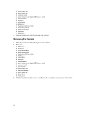
...VESA mount bracket d) system-board shield e) input/output (I/O) board shield f) WLAN card g) optical drive h) hard drive i) intrusion switch j) power and on -screen display (OSD) buttons board j) intrusion switch k) hard drive l) optical drive m) WLAN card n) input/output (I/O) board ...and disconnect the camera cable. Removing the Camera 1. f) power supply unit g) power-supply fan h) converter board i) power and on -screen display (OSD) buttons board k) converter board l) processor fan m) power supply unit n) heat-sink assembly o) power-supply fan p) system board q) display panel 3. Follow the...
...VESA mount bracket d) system-board shield e) input/output (I/O) board shield f) WLAN card g) optical drive h) hard drive i) intrusion switch j) power and on -screen display (OSD) buttons board j) intrusion switch k) hard drive l) optical drive m) WLAN card n) input/output (I/O) board ...and disconnect the camera cable. Removing the Camera 1. f) power supply unit g) power-supply fan h) converter board i) power and on -screen display (OSD) buttons board k) converter board l) processor fan m) power supply unit n) heat-sink assembly o) power-supply fan p) system board q) display panel 3. Follow the...

Owner's Manual
Page 41
Installing the Camera 1. Follow the procedures in After Working Inside Your Computer. 41 Connect the camera cable and fix the latch. 3. Tighten the screws to secure the camera to the chassis. 2. Install: a) display panel b) system board c) power-supply fan d) heat-sink assembly e) power supply unit f) processor fan g) converter board h) power and on-screen display (OSD) buttons board i) intrusion switch j) hard drive k) optical drive l) WLAN card m) input/output (I/O) board shield n) system-board shield o) VESA mount bracket p) back cover q) VESA stand 4.
Installing the Camera 1. Follow the procedures in After Working Inside Your Computer. 41 Connect the camera cable and fix the latch. 3. Tighten the screws to secure the camera to the chassis. 2. Install: a) display panel b) system board c) power-supply fan d) heat-sink assembly e) power supply unit f) processor fan g) converter board h) power and on-screen display (OSD) buttons board i) intrusion switch j) hard drive k) optical drive l) WLAN card m) input/output (I/O) board shield n) system-board shield o) VESA mount bracket p) back cover q) VESA stand 4.

Owner's Manual
Page 50
... in operating system environment. • Block Sleep (S3 state) - NOTE: When enabled, the fan runs at the time you block entering to AC power supply. Time is connected to sleep (S3 state) in S4 and S5 This option is set to turn off state when triggered by default. fields. •... fan. The system will periodically sense the nearby wireless connection while the system is disabled by default. This option is enabled, the feature will power up from standby. • Enable USB Wake Support - Wake-up on days selected above . This option is disabled by this option is ...
... in operating system environment. • Block Sleep (S3 state) - NOTE: When enabled, the fan runs at the time you block entering to AC power supply. Time is connected to sleep (S3 state) in S4 and S5 This option is set to turn off state when triggered by default. fields. •... fan. The system will periodically sense the nearby wireless connection while the system is disabled by default. This option is enabled, the feature will power up from standby. • Enable USB Wake Support - Wake-up on days selected above . This option is disabled by this option is ...
Owner's Manual
Page 60
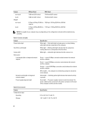
...a good 10 Mbps connection exists between the network and the computer. Green- Off (no light) - The power supply is functional. Controls and Lights Feature Power button light Hard Drive activity light Camera LED Back panel: Link integrity light on integrated network adapter : Network ...activity light on and is turned on integrated network adapter Power supply diagnostic light Specification White light - Blinking white light indicates that network activity is reading data from or writing data to 149 &#...
...a good 10 Mbps connection exists between the network and the computer. Green- Off (no light) - The power supply is functional. Controls and Lights Feature Power button light Hard Drive activity light Camera LED Back panel: Link integrity light on integrated network adapter : Network ...activity light on and is turned on integrated network adapter Power supply diagnostic light Specification White light - Blinking white light indicates that network activity is reading data from or writing data to 149 &#...

Setup And Features Information Tech Sheet
Page 3
...3.0 connector 13. Figure 4. USB Connection 3 USB 2.0 connectors (2) 7. network connector 11. Connect the keyboard or mouse. power connector 10. keyboard connector Quick Setup WARNING: Before you did not order. 1. HDMI-out connector 6. USB 2.0 connectors (2)...additional best practices information, see www.dell.com/regulatory_compliance NOTE: Some devices may not be included if you begin any of the procedures in this section, read the safety information that shipped with your computer. power-supply diagnostic button 3. power-supply diagnostic light 2. mouse connector 9....
...3.0 connector 13. Figure 4. USB Connection 3 USB 2.0 connectors (2) 7. network connector 11. Connect the keyboard or mouse. power connector 10. keyboard connector Quick Setup WARNING: Before you did not order. 1. HDMI-out connector 6. USB 2.0 connectors (2)...additional best practices information, see www.dell.com/regulatory_compliance NOTE: Some devices may not be included if you begin any of the procedures in this section, read the safety information that shipped with your computer. power-supply diagnostic button 3. power-supply diagnostic light 2. mouse connector 9....

Setup And Features Information Tech Sheet
Page 5
... this document in compliance with the requirements of the official Mexican standards (NOM). Voltaje de alimentación Frecuencia 100-240 VAC 50-60 Hz 5 Power Coin-cell battery Power Supply Unit (PSU): Voltage Wattage Maximum heat dissipation 3 V CR2032 lithium coin-cell 100 VAC to 95 °F) Information para NOM (únicamente para Mé...
... this document in compliance with the requirements of the official Mexican standards (NOM). Voltaje de alimentación Frecuencia 100-240 VAC 50-60 Hz 5 Power Coin-cell battery Power Supply Unit (PSU): Voltage Wattage Maximum heat dissipation 3 V CR2032 lithium coin-cell 100 VAC to 95 °F) Information para NOM (únicamente para Mé...


