
Owner's Manual
Page 3
...-Board Shield...15 Installing the System-Board Shield...16 Removing the Converter Board...16 Installing the Converter Board...17 Removing the Coin-Cell Battery...17 Installing the Coin-Cell Battery...17 Removing the Optical Drive...17 Installing the Optical Drive...19 Removing the Hard Drive...19 Installing the Hard Drive...20 Removing the Intrusion Switch...21 Installing the Intrusion Switch...22...
...-Board Shield...15 Installing the System-Board Shield...16 Removing the Converter Board...16 Installing the Converter Board...17 Removing the Coin-Cell Battery...17 Installing the Coin-Cell Battery...17 Removing the Optical Drive...17 Installing the Optical Drive...19 Removing the Hard Drive...19 Installing the Hard Drive...20 Removing the Intrusion Switch...21 Installing the Intrusion Switch...22...

Owner's Manual
Page 9
System Overview Figure 1. processor fan 5. memory module 9 2 Removing and Installing Components This section provides detailed information on how to remove or install the components from your computer. power supply unit (PSU) 2. hard drive 4. camera 3. heat sink 8. heat sink assembly 7. Inside View 1. coin-cell battery 6.
System Overview Figure 1. processor fan 5. memory module 9 2 Removing and Installing Components This section provides detailed information on how to remove or install the components from your computer. power supply unit (PSU) 2. hard drive 4. camera 3. heat sink 8. heat sink assembly 7. Inside View 1. coin-cell battery 6.

Owner's Manual
Page 19
... procedures in Before Working Inside Your Computer. 2. Remove the: a) VESA stand b) back cover c) VESA mount bracket 3. Remove the screw that secure the optical drive to the optical drive. 3. Slide and lift the hard-drive bracket away from the hard drive. 4. Connect the optical-drive cable. 5. Tighten the screws that secure the optical-drive bracket to the computer. 6. Install the: a) back...
... procedures in Before Working Inside Your Computer. 2. Remove the: a) VESA stand b) back cover c) VESA mount bracket 3. Remove the screw that secure the optical drive to the optical drive. 3. Slide and lift the hard-drive bracket away from the hard drive. 4. Connect the optical-drive cable. 5. Tighten the screws that secure the optical-drive bracket to the computer. 6. Install the: a) back...

Owner's Manual
Page 20
... hard drive to the hard drive. For a 2.5-inch hard drive, remove the screws that secure the hard-drive case to the hard-drive bracket. For a 3.5-inch hard drive, remove the screws that secure the hard-drive case to the hard-drive bracket. Installing the Hard Drive 1. For a 3.5-inch hard drive, slide the hard drive into the notches on the computer. 4. Align and place the hard-drive bracket on the hard-drive bracket. 6. Connect the hard-drive cables to the hard-drive bracket 5. Remove...
... hard drive to the hard drive. For a 2.5-inch hard drive, remove the screws that secure the hard-drive case to the hard-drive bracket. For a 3.5-inch hard drive, remove the screws that secure the hard-drive case to the hard-drive bracket. Installing the Hard Drive 1. For a 3.5-inch hard drive, slide the hard drive into the notches on the computer. 4. Align and place the hard-drive bracket on the hard-drive bracket. 6. Connect the hard-drive cables to the hard-drive bracket 5. Remove...

Owner's Manual
Page 32
Disconnect all the cables that secure the system board to the system board. 4. Remove the screws that are connected to the computer. 5. Removing the System Board 1. Lift and remove the system board from the chassis. Follow the procedures in Before Working Inside ... 2. System Board Layout The following image displays the system board layout of the computer. 32 Remove the: a) VESA stand b) back cover c) VESA mount bracket d) system-board shield e) memory f) optical drive g) hard drive h) heat-sink assembly i) power supply unit j) input/output (I/O) board shield k) converter board ...
Disconnect all the cables that secure the system board to the system board. 4. Remove the screws that are connected to the computer. 5. Removing the System Board 1. Lift and remove the system board from the chassis. Follow the procedures in Before Working Inside ... 2. System Board Layout The following image displays the system board layout of the computer. 32 Remove the: a) VESA stand b) back cover c) VESA mount bracket d) system-board shield e) memory f) optical drive g) hard drive h) heat-sink assembly i) power supply unit j) input/output (I/O) board shield k) converter board ...

Owner's Manual
Page 34
.../output (I /O) board shield k) converter board l) power-supply fan m) system board 3. Remove the: a) VESA stand b) back cover c) VESA mount bracket d) system-board shield e) memory f) optical drive g) hard drive h) heat-sink assembly i) power supply unit j) input/output (I /O) board shield d) power supply unit e) heat-sink assembly f) hard drive g) optical drive h) memory i) system-board shield j) VESA mount bracket k) back cover l) VESA...
.../output (I /O) board shield k) converter board l) power-supply fan m) system board 3. Remove the: a) VESA stand b) back cover c) VESA mount bracket d) system-board shield e) memory f) optical drive g) hard drive h) heat-sink assembly i) power supply unit j) input/output (I /O) board shield d) power supply unit e) heat-sink assembly f) hard drive g) optical drive h) memory i) system-board shield j) VESA mount bracket k) back cover l) VESA...

Owner's Manual
Page 36
... board 3. Follow the procedures in After Working Inside Your Computer. Lift and remove the antenna module. 36 Remove the: a) VESA stand b) back cover c) VESA mount bracket d) system-board shield e) input/output (I /O) board shield e) power supply unit f) heat-sink assembly g) hard drive h) optical drive i) memory j) system-board shield k) VESA mount bracket l) back cover m) VESA stand 5. Unthread...
... board 3. Follow the procedures in After Working Inside Your Computer. Lift and remove the antenna module. 36 Remove the: a) VESA stand b) back cover c) VESA mount bracket d) system-board shield e) input/output (I /O) board shield e) power supply unit f) heat-sink assembly g) hard drive h) optical drive i) memory j) system-board shield k) VESA mount bracket l) back cover m) VESA stand 5. Unthread...

Owner's Manual
Page 37
... the antenna module to the chassis 3. Removing the Display Panel 1. Install: a) system board b) power-supply fan c) heat-sink assembly d) power supply unit e) processor fan f) converter board g) power and on-screen display (OSD) buttons board h) intrusion switch i) hard drive j) optical drive k) WLAN card l) input/output (I /O) board shield f) WLAN card g) optical drive h) hard drive i) intrusion switch j) power and on...
... the antenna module to the chassis 3. Removing the Display Panel 1. Install: a) system board b) power-supply fan c) heat-sink assembly d) power supply unit e) processor fan f) converter board g) power and on-screen display (OSD) buttons board h) intrusion switch i) hard drive j) optical drive k) WLAN card l) input/output (I /O) board shield f) WLAN card g) optical drive h) hard drive i) intrusion switch j) power and on...
Owner's Manual
Page 40
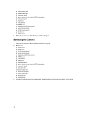
... bracket d) system-board shield e) input/output (I/O) board shield f) WLAN card g) optical drive h) hard drive i) intrusion switch j) power and on -screen display (OSD) buttons board j) intrusion switch k) hard drive l) optical drive m) WLAN card n) input/output (I/O) board shield o) system-board shield p) VESA mount bracket q) back cover r) VESA stand 7. Remove the screws that secure the camera to the chassis. 40
... bracket d) system-board shield e) input/output (I/O) board shield f) WLAN card g) optical drive h) hard drive i) intrusion switch j) power and on -screen display (OSD) buttons board j) intrusion switch k) hard drive l) optical drive m) WLAN card n) input/output (I/O) board shield o) system-board shield p) VESA mount bracket q) back cover r) VESA stand 7. Remove the screws that secure the camera to the chassis. 40

Owner's Manual
Page 43
...the Dell logo appears, you can: • Access System Setup by pressing key • Bring up the one-time boot menu by pressing key The one-time boot menu displays the devices that you make are : • Removable Drive (if available) • STXXXX Drive NOTE: XXX denotes the SATA drive number.... hard drive). NOTE: For most of the system setup options, changes that you can : • Change the NVRAM settings after you can boot from including the diagnostic option. From the System Setup, you add or remove hardware • View the system hardware configuration • Enable or disable ...
...the Dell logo appears, you can: • Access System Setup by pressing key • Bring up the one-time boot menu by pressing key The one-time boot menu displays the devices that you make are : • Removable Drive (if available) • STXXXX Drive NOTE: XXX denotes the SATA drive number.... hard drive). NOTE: For most of the system setup options, changes that you can : • Change the NVRAM settings after you can boot from including the diagnostic option. From the System Setup, you add or remove hardware • View the system hardware configuration • Enable or disable ...

Statement of Volatility
Page 2
... 2013 Dell Inc. May also - Trademarks used in GB. User Non Volatile optical media. Secondary power loss (removing the on-board coin-cell battery) destroys system data on the memory (DDR3). Description Hard drive(s) CDROM/RW/ DVD/ DVD+RW/ Diskette Drives Reference ...Designator Volatility Description User Accessible for external data Remedial Action (Action necessary to prevent loss of data) User Non Volatile magnetic media, Yes replaceable various sizes in this text: Dell™, the DELL logo, OptiPlex&#...
... 2013 Dell Inc. May also - Trademarks used in GB. User Non Volatile optical media. Secondary power loss (removing the on-board coin-cell battery) destroys system data on the memory (DDR3). Description Hard drive(s) CDROM/RW/ DVD/ DVD+RW/ Diskette Drives Reference ...Designator Volatility Description User Accessible for external data Remedial Action (Action necessary to prevent loss of data) User Non Volatile magnetic media, Yes replaceable various sizes in this text: Dell™, the DELL logo, OptiPlex&#...


