
Owner's Manual
Page 4
... Card)...35 Removing the Antenna Module...36 Installing the Antenna Module...37 Removing the Display Panel...37 Installing the Display Panel...39 Removing the Camera...40 Installing the Camera...41 3 System Setup...43 Boot Sequence...43 Navigation Keys...43 System Setup Options...44 Updating the BIOS ...53 System and Setup Password...53...
... Card)...35 Removing the Antenna Module...36 Installing the Antenna Module...37 Removing the Display Panel...37 Installing the Display Panel...39 Removing the Camera...40 Installing the Camera...41 3 System Setup...43 Boot Sequence...43 Navigation Keys...43 System Setup Options...44 Updating the BIOS ...53 System and Setup Password...53...

Owner's Manual
Page 9
camera 3. hard drive 4. heat sink 8. Inside View 1. processor fan 5. heat sink assembly 7. memory module 9 coin-cell battery 6. power supply unit (PSU) 2. 2 Removing and Installing Components This section provides detailed information on how to remove or install the components from your computer. System Overview Figure 1.
camera 3. hard drive 4. heat sink 8. Inside View 1. processor fan 5. heat sink assembly 7. memory module 9 coin-cell battery 6. power supply unit (PSU) 2. 2 Removing and Installing Components This section provides detailed information on how to remove or install the components from your computer. System Overview Figure 1.
Owner's Manual
Page 40
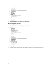
Removing the Camera 1. Remove the: a) VESA stand b) back cover c) VESA mount bracket d) system-board shield e) input/output (I/O) board shield f) WLAN... VESA mount bracket q) back cover r) VESA stand 7. Follow the procedures in Before Working Inside Your Computer. 2. Lift the latch and disconnect the camera cable. f) power supply unit g) power-supply fan h) converter board i) power and on -screen display (OSD) buttons board k) converter board l) ...display panel 3. Follow the procedures in After Working Inside Your Computer. Remove the screws that secure the camera to the chassis. 40
Removing the Camera 1. Remove the: a) VESA stand b) back cover c) VESA mount bracket d) system-board shield e) input/output (I/O) board shield f) WLAN... VESA mount bracket q) back cover r) VESA stand 7. Follow the procedures in Before Working Inside Your Computer. 2. Lift the latch and disconnect the camera cable. f) power supply unit g) power-supply fan h) converter board i) power and on -screen display (OSD) buttons board k) converter board l) ...display panel 3. Follow the procedures in After Working Inside Your Computer. Remove the screws that secure the camera to the chassis. 40

Owner's Manual
Page 41
Follow the procedures in After Working Inside Your Computer. 41 Install: a) display panel b) system board c) power-supply fan d) heat-sink assembly e) power supply unit f) processor fan g) converter board h) power and on-screen display (OSD) buttons board i) intrusion switch j) hard drive k) optical drive l) WLAN card m) input/output (I/O) board shield n) system-board shield o) VESA mount bracket p) back cover q) VESA stand 4. Tighten the screws to secure the camera to the chassis. 2. Installing the Camera 1. Connect the camera cable and fix the latch. 3.
Follow the procedures in After Working Inside Your Computer. 41 Install: a) display panel b) system board c) power-supply fan d) heat-sink assembly e) power supply unit f) processor fan g) converter board h) power and on-screen display (OSD) buttons board i) intrusion switch j) hard drive k) optical drive l) WLAN card m) input/output (I/O) board shield n) system-board shield o) VESA mount bracket p) back cover q) VESA stand 4. Tighten the screws to secure the camera to the chassis. 2. Installing the Camera 1. Connect the camera cable and fix the latch. 3.
Owner's Manual
Page 46
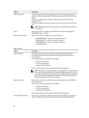
... to use the admin password to this password take effect immediately. If Boot Support is enabled, the system is already set by default. • Enable Camera - Option USB Configuration Audio Miscellaneous Devices Table 4. You cannot set an admin password if a system password or an HDD password is allowed to boot any...
... to use the admin password to this password take effect immediately. If Boot Support is enabled, the system is already set by default. • Enable Camera - Option USB Configuration Audio Miscellaneous Devices Table 4. You cannot set an admin password if a system password or an HDD password is allowed to boot any...

Owner's Manual
Page 59
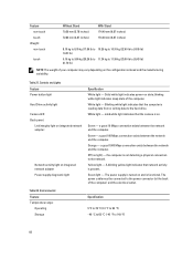
... Hz 100 VAC - 240 VAC Maximum 2.90 A Maximum 1.45 A 3 V CR2032 lithium coin cell Table 24. Stand Feature Tilt Specification -5 degrees to 30 degrees Table 26. Camera (optional) Feature Image resolution Video resolution Diagonal viewing angle Specification 2.0 megapixel FHD (1080p) 66.2 degrees Table 25. Physical Dimensions Feature Without Stand Width 574.00...
... Hz 100 VAC - 240 VAC Maximum 2.90 A Maximum 1.45 A 3 V CR2032 lithium coin cell Table 24. Stand Feature Tilt Specification -5 degrees to 30 degrees Table 26. Camera (optional) Feature Image resolution Video resolution Diagonal viewing angle Specification 2.0 megapixel FHD (1080p) 66.2 degrees Table 25. Physical Dimensions Feature Without Stand Width 574.00...
Owner's Manual
Page 60
...back of the computer. blinking white light indicates sleep state of the computer) and the electrical outlet. Blinking white light indicates that the camera is reading data from or writing data to 149 °F) 60 solid while light indicates that the computer is on. a good 10 ...kg to 11.99 kg (25.00 lb to the network. Table 27. Controls and Lights Feature Power button light Hard Drive activity light Camera LED Back panel: Link integrity light on integrated network adapter : Network activity light on the configuration ordered and the manufacturing variability. White light...
...back of the computer. blinking white light indicates sleep state of the computer) and the electrical outlet. Blinking white light indicates that the camera is reading data from or writing data to 149 °F) 60 solid while light indicates that the computer is on. a good 10 ...kg to 11.99 kg (25.00 lb to the network. Table 27. Controls and Lights Feature Power button light Hard Drive activity light Camera LED Back panel: Link integrity light on integrated network adapter : Network activity light on the configuration ordered and the manufacturing variability. White light...

Setup And Features Information Tech Sheet
Page 1
camera (optional) 3. camera tilt wheel (touch screen) / camera slide bar (non-touch screen) Regulatory Model: W04C Regulatory Type: W04C002 2013 - 02 Dell OptiPlex 9020 AlO Setup And Features Information About Warnings WARNING: A WARNING indicates a potential for property damage, personal injury, or death. Front View Figure 1. microphone (left) 2. Front View 1.
camera (optional) 3. camera tilt wheel (touch screen) / camera slide bar (non-touch screen) Regulatory Model: W04C Regulatory Type: W04C002 2013 - 02 Dell OptiPlex 9020 AlO Setup And Features Information About Warnings WARNING: A WARNING indicates a potential for property damage, personal injury, or death. Front View Figure 1. microphone (left) 2. Front View 1.

Setup And Features Information Tech Sheet
Page 2
hard-drive activity light 11. Back View 1. display 7. optical drive eject button 9. power button 12. stand Figure 2. 4. VESA cover 4. memory card reader 2 5. microphone connector 7. On-Screen Display (OSD) buttons (3) 10. security cable slot 3. camera LED 5. optical drive (optional) Back View 8. USB 3.0 connectors (2) 6. microphone (right) NOTE: The location of microphone varies in the non-touch version. 6. back panel connectors 2. headphone connector
hard-drive activity light 11. Back View 1. display 7. optical drive eject button 9. power button 12. stand Figure 2. 4. VESA cover 4. memory card reader 2 5. microphone connector 7. On-Screen Display (OSD) buttons (3) 10. security cable slot 3. camera LED 5. optical drive (optional) Back View 8. USB 3.0 connectors (2) 6. microphone (right) NOTE: The location of microphone varies in the non-touch version. 6. back panel connectors 2. headphone connector


