
User Manual
Page 2
headphone connector Figure 3. power supply diagnostic button 2 3. line-out connector power supply diagnostic light 2. VESA cover 4. microphone connector 7. memory card reader Back Panel View 5. Back View Figure 2. Back View 1. back panel connectors 2. security cable slot 3. USB 3.0 connectors (2) 6. Back Panel View 1. VGA-out connector 4.
headphone connector Figure 3. power supply diagnostic button 2 3. line-out connector power supply diagnostic light 2. VESA cover 4. microphone connector 7. memory card reader Back Panel View 5. Back View Figure 2. Back View 1. back panel connectors 2. security cable slot 3. USB 3.0 connectors (2) 6. Back Panel View 1. VGA-out connector 4.
Owner's Manual
Page 3
......5 Turning Off Your Computer...6 After Working Inside Your Computer...6 2 Removing and Installing Components 7 Recommended Tools...7 Removing the VESA Stand...7 Installing the VESA Stand...8 Removing the Back Cover...8 Installing the Back Cover...9 Removing the Memory...9 Installing the Memory...10 Removing the... VESA Mount Bracket...10 Installing the VESA Mount Bracket...11 Removing the Converter Board...11 Installing the Converter Board...12 Removing the System-Board Shield...
......5 Turning Off Your Computer...6 After Working Inside Your Computer...6 2 Removing and Installing Components 7 Recommended Tools...7 Removing the VESA Stand...7 Installing the VESA Stand...8 Removing the Back Cover...8 Installing the Back Cover...9 Removing the Memory...9 Installing the Memory...10 Removing the... VESA Mount Bracket...10 Installing the VESA Mount Bracket...11 Removing the Converter Board...11 Installing the Converter Board...12 Removing the System-Board Shield...
Owner's Manual
Page 7
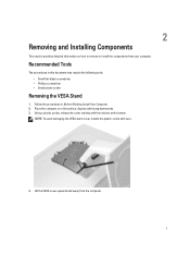
NOTE: To avoid damaging the VESA stand cover, handle the plastic scribe with the notches at the bottom. Place the computer on how to remove or install the components from the ... the procedures in this document may require the following tools: • Small flat-blade screwdriver • Phillips screwdriver • Small plastic scribe Removing the VESA Stand 1. Lift the VESA cover upwards and away from your computer. 2 Removing and Installing Components This section provides detailed information on a flat surface, display side facing downwards. 3.
NOTE: To avoid damaging the VESA stand cover, handle the plastic scribe with the notches at the bottom. Place the computer on how to remove or install the components from the ... the procedures in this document may require the following tools: • Small flat-blade screwdriver • Phillips screwdriver • Small plastic scribe Removing the VESA Stand 1. Lift the VESA cover upwards and away from your computer. 2 Removing and Installing Components This section provides detailed information on a flat surface, display side facing downwards. 3.

Owner's Manual
Page 8
... the procedures in After Working Inside Your Computer. Installing the VESA Stand 1. Remove the screws from the computer. Remove the VESA stand. 3. 5. Follow the procedures inBefore Working Inside Your Computer. 2. Place and press the VESA cover on the back of the computer. 8 Removing the Back... Cover 1. Align and place the VESA stand on the computer, till it clicks...
... the procedures in After Working Inside Your Computer. Installing the VESA Stand 1. Remove the screws from the computer. Remove the VESA stand. 3. 5. Follow the procedures inBefore Working Inside Your Computer. 2. Place and press the VESA cover on the back of the computer. 8 Removing the Back... Cover 1. Align and place the VESA stand on the computer, till it clicks...
Owner's Manual
Page 9
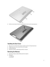
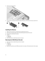
Tighten the screws to secure the back cover to the computer. 3. Remove the: a) VESA stand b) back cover 9 Lift the cover and remove it from the computer using the notches near the input/output panel. Place the cover on the back of the computer using the notches near the input/output panel. 2. Install the VESA stand. 4. Removing the Memory 1. Installing the Back Cover 1. Follow the procedures in After Working Inside Your Computer. 4. Follow the procedures in Before Working Inside Your Computer. 2.
Tighten the screws to secure the back cover to the computer. 3. Remove the: a) VESA stand b) back cover 9 Lift the cover and remove it from the computer using the notches near the input/output panel. Place the cover on the back of the computer using the notches near the input/output panel. 2. Install the VESA stand. 4. Removing the Memory 1. Installing the Back Cover 1. Follow the procedures in After Working Inside Your Computer. 4. Follow the procedures in Before Working Inside Your Computer. 2.
Owner's Manual
Page 10
...back into its connector. Follow the procedures in the system-board connector. 2. 3. Pry the retention clips away from the computer. 10 Removing the VESA Mount Bracket 1. Lift the memory shield outwards. 4. Press down on the memory-card with the tab in Before Working Inside Your Computer. 2.... Remove the screws that secure the VESA mount bracket to secure them in After Working Inside Your Computer. Install the: a) back cover b) VESA stand 5. Lift the bracket away from the memory module until the release tabs spring back...
...back into its connector. Follow the procedures in the system-board connector. 2. 3. Pry the retention clips away from the computer. 10 Removing the VESA Mount Bracket 1. Lift the memory shield outwards. 4. Press down on the memory-card with the tab in Before Working Inside Your Computer. 2.... Remove the screws that secure the VESA mount bracket to secure them in After Working Inside Your Computer. Install the: a) back cover b) VESA stand 5. Lift the bracket away from the memory module until the release tabs spring back...

Owner's Manual
Page 11
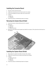
... the convertor board away from the converter board. Tighten the screws to secure the VESA mount bracket to the computer. Install the: a) back cover b) VESA stand 4. Disconnect the backlight and converter cables from the computer. 11 Remove the: a) VESA stand b) back cover 3. Remove the screws that secure the converter board to the computer...
... the convertor board away from the converter board. Tighten the screws to secure the VESA mount bracket to the computer. Install the: a) back cover b) VESA stand 4. Disconnect the backlight and converter cables from the computer. 11 Remove the: a) VESA stand b) back cover 3. Remove the screws that secure the converter board to the computer...
Owner's Manual
Page 12
... 1. Installing the System-Board Shield 1. Tighten the screws that secure the converter board to the computer. 3. Install the: a) VESA mount bracket b) back cover c) VESA stand 4. Place the convertor board into its place. 2. Follow the procedures in After Working Inside Your Computer. Remove the screws ...-board shield to the converter board. 4. Follow the procedures in After Working Inside Your Computer. 12 Remove the: a) VESA stand b) back cover c) VESA mount bracket 3. Lift the system-board shield away from the computer. Align and place the system-board shield on the...
... 1. Installing the System-Board Shield 1. Tighten the screws that secure the converter board to the computer. 3. Install the: a) VESA mount bracket b) back cover c) VESA stand 4. Place the convertor board into its place. 2. Follow the procedures in After Working Inside Your Computer. Remove the screws ...-board shield to the converter board. 4. Follow the procedures in After Working Inside Your Computer. 12 Remove the: a) VESA stand b) back cover c) VESA mount bracket 3. Lift the system-board shield away from the computer. Align and place the system-board shield on the...
Owner's Manual
Page 13
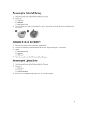
... into its slot on the system board. 2. Install: a) system-board shield b) base cover c) VESA stand 4. Follow the procedures in After Working Inside Your Computer. Remove the: a) VESA stand b) back cover c) system-board shield 3. Remove the: a) VESA stand b) back cover c) VESA mount bracket 3. Removing the Optical Drive 1. Press the release latch away from the socket...
... into its slot on the system board. 2. Install: a) system-board shield b) base cover c) VESA stand 4. Follow the procedures in After Working Inside Your Computer. Remove the: a) VESA stand b) back cover c) system-board shield 3. Remove the: a) VESA stand b) back cover c) VESA mount bracket 3. Removing the Optical Drive 1. Press the release latch away from the socket...
Owner's Manual
Page 15
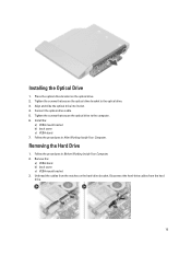
... to the computer. 6. Removing the Hard Drive 1. Align and slide the optical drive into its slot. 4. Connect the optical-drive cable. 5. Install the: a) VESA mount bracket b) back cover c) VESA stand 7. Disconnect the hard-drive cables from the notches on the optical drive. 2. Place the optical-drive bracket on the hard-drive bracket.... 15 Installing the Optical Drive 1. Follow the procedures in After Working Inside Your Computer. Follow the procedures in Before Working Inside Your Computer. 2. Remove the: a) VESA stand b) back cover c) VESA mount bracket 3.
... to the computer. 6. Removing the Hard Drive 1. Align and slide the optical drive into its slot. 4. Connect the optical-drive cable. 5. Install the: a) VESA mount bracket b) back cover c) VESA stand 7. Disconnect the hard-drive cables from the notches on the optical drive. 2. Place the optical-drive bracket on the hard-drive bracket.... 15 Installing the Optical Drive 1. Follow the procedures in After Working Inside Your Computer. Follow the procedures in Before Working Inside Your Computer. 2. Remove the: a) VESA stand b) back cover c) VESA mount bracket 3.

Owner's Manual
Page 17
Removing the Intrusion Switch 1. Follow the procedures in After Working Inside Your Computer. Remove the: a) VESA stand b) back cover c) VESA mount bracket d) system-board shield 3. Unthread the cable from the notches on the system board. Remove the screws that secure the intrusion switch to the chassis. Lift the intrusion switch and remove it from the connector on the computer. 4. Disconnect the intrusion cable from the computer. 17 Follow the procedures in Before Working Inside Your Computer. 2. a) VESA mount bracket b) back cover c) VESA stand 6.
Removing the Intrusion Switch 1. Follow the procedures in After Working Inside Your Computer. Remove the: a) VESA stand b) back cover c) VESA mount bracket d) system-board shield 3. Unthread the cable from the notches on the system board. Remove the screws that secure the intrusion switch to the chassis. Lift the intrusion switch and remove it from the connector on the computer. 4. Disconnect the intrusion cable from the computer. 17 Follow the procedures in Before Working Inside Your Computer. 2. a) VESA mount bracket b) back cover c) VESA stand 6.

Owner's Manual
Page 18
... the WLAN card from the connector. 18 Follow the procedures in After Working Inside Your Computer. Install: a) system-board shield b) VESA mount bracket c) back cover d) VESA stand 4. Remove the: a) VESA stand b) back cover c) VESA mount bracket d) system-board shield 3. Disconnect the WLAN cables. Thread the cable along the notches on the system board. 3. Remove...
... the WLAN card from the connector. 18 Follow the procedures in After Working Inside Your Computer. Install: a) system-board shield b) VESA mount bracket c) back cover d) VESA stand 4. Remove the: a) VESA stand b) back cover c) VESA mount bracket d) system-board shield 3. Disconnect the WLAN cables. Thread the cable along the notches on the system board. 3. Remove...

Owner's Manual
Page 19
... in Before Working Inside Your Computer. 2. Remove the screws that secures the fan bracket to the chassis. Remove the: a) VESA stand b) back cover c) VESA mount bracket d) system-board shield 3. Lift the fan bracket away from the computer. 19 Tighten the screws to secure the .... 4. Removing the Power-Supply Fan 1. Follow the procedures in After Working Inside Your Computer. Install: a) system-board shield b) VESA mount bracket c) back cover d) VESA stand 5. Connect the WLAN cables. 4. Align and place the WLAN card on the connector. 2. Remove the screw that secure the...
... in Before Working Inside Your Computer. 2. Remove the screws that secures the fan bracket to the chassis. Remove the: a) VESA stand b) back cover c) VESA mount bracket d) system-board shield 3. Lift the fan bracket away from the computer. 19 Tighten the screws to secure the .... 4. Removing the Power-Supply Fan 1. Follow the procedures in After Working Inside Your Computer. Install: a) system-board shield b) VESA mount bracket c) back cover d) VESA stand 5. Connect the WLAN cables. 4. Align and place the WLAN card on the connector. 2. Remove the screw that secure the...

Owner's Manual
Page 20
... procedures in Before Working Inside Your Computer. 2. Removing the Power Supply Unit (PSU) 1. Install: a) system-board shield b) VESA mount bracket c) back cover d) VESA stand 5. Press the tab and disconnect the power-supply cable from the connector on from the hooks in the computer. 20 Installing... the Power-Supply Fan 1. Align and place the fan bracket on the system board. Remove the: a) VESA stand b) back cover c) VESA mount bracket d) system-board shield e) input/output board shield f) power-supply fan 3. Place the power-supply fan on the...
... procedures in Before Working Inside Your Computer. 2. Removing the Power Supply Unit (PSU) 1. Install: a) system-board shield b) VESA mount bracket c) back cover d) VESA stand 5. Press the tab and disconnect the power-supply cable from the connector on from the hooks in the computer. 20 Installing... the Power-Supply Fan 1. Align and place the fan bracket on the system board. Remove the: a) VESA stand b) back cover c) VESA mount bracket d) system-board shield e) input/output board shield f) power-supply fan 3. Place the power-supply fan on the...

Owner's Manual
Page 21
Remove the screws securing the power supply unit to the chassis. 3. Tighten the screws to secure the power supply unit to the chassis. Connect the power-supply cable to the connector on the computer. 2. Installing the Power Supply Unit 1. Place the power supply unit on the system board. 5. 4. Thread the cable on the hooks in the computer. 4. Install: a) power-supply fan b) input/output board shield c) system-board shield d) VESA mount bracket e) back cover f) VESA stand 21 Lift the PSU up and remove it from the computer.
Remove the screws securing the power supply unit to the chassis. 3. Tighten the screws to secure the power supply unit to the chassis. Connect the power-supply cable to the connector on the computer. 2. Installing the Power Supply Unit 1. Place the power supply unit on the system board. 5. 4. Thread the cable on the hooks in the computer. 4. Install: a) power-supply fan b) input/output board shield c) system-board shield d) VESA mount bracket e) back cover f) VESA stand 21 Lift the PSU up and remove it from the computer.

Owner's Manual
Page 22
...procedures in Before Working Inside Your Computer. 2. Align and place the heat-sink assembly on the computer. 2. Remove the: a) VESA stand b) back cover c) VESA mount bracket d) system-board shield e) power-supply fan 3. Removing the Heat-Sink Assembly 1. Remove the screws that secure the ...thermal module to the chassis. 3. Install: a) system-board shield b) VESA mount bracket c) back cover d) VESA stand 4. Lift the input/output panel away from the computer. Installing the Heat-Sink Assembly 1. Tighten the screws to secure...
...procedures in Before Working Inside Your Computer. 2. Align and place the heat-sink assembly on the computer. 2. Remove the: a) VESA stand b) back cover c) VESA mount bracket d) system-board shield e) power-supply fan 3. Removing the Heat-Sink Assembly 1. Remove the screws that secure the ...thermal module to the chassis. 3. Install: a) system-board shield b) VESA mount bracket c) back cover d) VESA stand 4. Lift the input/output panel away from the computer. Installing the Heat-Sink Assembly 1. Tighten the screws to secure...

Owner's Manual
Page 25
Tighten the screws that secure the power connector to the chassis. 4. Remove the: a) VESA stand b) back cover 3. Tighten the screws to secure the input/output board shield to the input/output shield. 5. Follow the procedures in Before Working ...Inside Your Computer. 2. Pass the power connector and fix it to the socket. Install: a) power-supply fan b) system-board shield c) VESA mount bracket d) back cover e) VESA stand 7. Place the input/output panel on the computer. 3. Lift the power-button board from the board. Disconnect the power-button cable from...
Tighten the screws that secure the power connector to the chassis. 4. Remove the: a) VESA stand b) back cover 3. Tighten the screws to secure the input/output board shield to the input/output shield. 5. Follow the procedures in Before Working ...Inside Your Computer. 2. Pass the power connector and fix it to the socket. Install: a) power-supply fan b) system-board shield c) VESA mount bracket d) back cover e) VESA stand 7. Place the input/output panel on the computer. 3. Lift the power-button board from the board. Disconnect the power-button cable from...

Owner's Manual
Page 26
...Before Working Inside Your Computer. 2. Disconnect the processor-fan cable from the computer. 26 Removing the Processor Fan 1. Install: a) back cover b) VESA stand 4. Align and place the power-button board on the system board. Remove the screws that secure the processor fan to the board. 3.... the power-button cable to the system board and lift it away from the connector on the computer. 2. Remove the: a) VESA stand b) back cover c) VESA mount bracket d) system-board shield 3. Follow the procedures in After Working Inside Your Computer. Installing the Power-Button Board 1.
...Before Working Inside Your Computer. 2. Disconnect the processor-fan cable from the computer. 26 Removing the Processor Fan 1. Install: a) back cover b) VESA stand 4. Align and place the power-button board on the system board. Remove the screws that secure the processor fan to the board. 3.... the power-button cable to the system board and lift it away from the connector on the computer. 2. Remove the: a) VESA stand b) back cover c) VESA mount bracket d) system-board shield 3. Follow the procedures in After Working Inside Your Computer. Installing the Power-Button Board 1.

Owner's Manual
Page 27
...the screws to secure the processor fan to release it from its socket. Install: a) system-board shield b) VESA mount bracket c) back cover d) VESA stand 4. Remove the: a) VESA stand b) back cover c) VESA mount bracket d) system-board shield e) heat-sink assembly 3. Installing the Processor 1. Install: a) heat-sink... assembly b) system-board shield c) VESA mount bracket d) back cover e) VESA stand 4. Press the release lever down and then move it outward to the system board. 2. Lift the processor ...
...the screws to secure the processor fan to release it from its socket. Install: a) system-board shield b) VESA mount bracket c) back cover d) VESA stand 4. Remove the: a) VESA stand b) back cover c) VESA mount bracket d) system-board shield e) heat-sink assembly 3. Installing the Processor 1. Install: a) heat-sink... assembly b) system-board shield c) VESA mount bracket d) back cover e) VESA stand 4. Press the release lever down and then move it outward to the system board. 2. Lift the processor ...

Owner's Manual
Page 28
Lift the speakers from the connector on the system board. Follow the procedures in Before Working Inside Your Computer. 2. Remove the: a) VESA stand b) back cover c) VESA mount bracket d) system-board shield 3. Disconnect the right and left speaker cables from the computer. 28 Unthread the cables from the notches. 4. Remove the screws that secure the speaker to the chassis. Removing the Speakers 1.
Lift the speakers from the connector on the system board. Follow the procedures in Before Working Inside Your Computer. 2. Remove the: a) VESA stand b) back cover c) VESA mount bracket d) system-board shield 3. Disconnect the right and left speaker cables from the computer. 28 Unthread the cables from the notches. 4. Remove the screws that secure the speaker to the chassis. Removing the Speakers 1.


