Owner's Manual
Page 3
...-Board Shield...12 Installing the System-Board Shield...12 Removing the Coin-Cell Battery...13 Installing the Coin-Cell Battery...13 Removing the Optical Drive...13 Installing the Optical Drive...15 Removing the Hard Drive...15 Installing the Hard Drive...16 Removing the Intrusion Switch...17 Installing the Intrusion Switch...18 Removing the Wireless Local Area Network (WLAN) Card 18 Installing...
...-Board Shield...12 Installing the System-Board Shield...12 Removing the Coin-Cell Battery...13 Installing the Coin-Cell Battery...13 Removing the Optical Drive...13 Installing the Optical Drive...15 Removing the Hard Drive...15 Installing the Hard Drive...16 Removing the Intrusion Switch...17 Installing the Intrusion Switch...18 Removing the Wireless Local Area Network (WLAN) Card 18 Installing...
Owner's Manual
Page 15
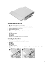
... Working Inside Your Computer. Install the: a) VESA mount bracket b) back cover c) VESA stand 7. Disconnect the hard-drive cables from the notches on the optical drive. 2. Tighten the screws that secure the optical drive to the optical drive. 3. Place the optical-drive bracket on the hard-drive bracket. Removing the Hard Drive 1. Installing the Optical Drive 1. Tighten the screws that secure the optical...
... Working Inside Your Computer. Install the: a) VESA mount bracket b) back cover c) VESA stand 7. Disconnect the hard-drive cables from the notches on the optical drive. 2. Tighten the screws that secure the optical drive to the optical drive. 3. Place the optical-drive bracket on the hard-drive bracket. Removing the Hard Drive 1. Installing the Optical Drive 1. Tighten the screws that secure the optical...

Owner's Manual
Page 16
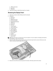
... hard-drive bracket to the hard-drive bracket. Tighten the screw that secure the hard drive to the hard-drive bracket. 3. Install: 16 For a 3.5-inch hard drive, remove the screws that secure the hard drive to the hard-drive bracket. 2. Tighten the screws that secure the hard drive to the hard drive. Thread the cables into the hard-drive bracket. Remove the screw that secure the hard-drive case to the hard-drive bracket. For a 2.5-inch hard drive...
... hard-drive bracket to the hard-drive bracket. Tighten the screw that secure the hard drive to the hard-drive bracket. 3. Install: 16 For a 3.5-inch hard drive, remove the screws that secure the hard drive to the hard-drive bracket. 2. Tighten the screws that secure the hard drive to the hard drive. Thread the cables into the hard-drive bracket. Remove the screw that secure the hard-drive case to the hard-drive bracket. For a 2.5-inch hard drive...

Owner's Manual
Page 29
... left speaker cables to the chassis. 2. Install: a) system-board shield b) VESA mount bracket c) back cover d) VESA stand 4. Removing the System Board 1. Remove the: a) VESA stand b) back cover c) VESA mount bracket d) system-board shield e) memory f) optical drive g) hard drive h) heat-sink assembly i) power supply unit j) input/output board shield k) converter board l) power-supply fan 3. Thread the...
... left speaker cables to the chassis. 2. Install: a) system-board shield b) VESA mount bracket c) back cover d) VESA stand 4. Removing the System Board 1. Remove the: a) VESA stand b) back cover c) VESA mount bracket d) system-board shield e) memory f) optical drive g) hard drive h) heat-sink assembly i) power supply unit j) input/output board shield k) converter board l) power-supply fan 3. Thread the...

Owner's Manual
Page 30
Installing the System Board 1. Tighten the screws to secure the system board to the base panel. 3. Place the system board on the computer. 2. 5. Lift and remove the system board from the chassis. Install: a) power-supply fan b) converter board c) input/output board shield d) power supply unit e) heat-sink assembly f) hard drive g) optical drive h) memory i) system-board shield 30
Installing the System Board 1. Tighten the screws to secure the system board to the base panel. 3. Place the system board on the computer. 2. 5. Lift and remove the system board from the chassis. Install: a) power-supply fan b) converter board c) input/output board shield d) power supply unit e) heat-sink assembly f) hard drive g) optical drive h) memory i) system-board shield 30
Owner's Manual
Page 31
... screws that secure the base panel to the chassis. Lift the base panel from the connector. Remove the: a) VESA stand b) back cover c) VESA mount bracket d) system-board shield e) input/output board shield f) WLAN card g) optical drive h) hard drive i) intrusion switch j) power-button board k) converter board l) power-supply fan m) power supply unit n) heat-sink assembly...
... screws that secure the base panel to the chassis. Lift the base panel from the connector. Remove the: a) VESA stand b) back cover c) VESA mount bracket d) system-board shield e) input/output board shield f) WLAN card g) optical drive h) hard drive i) intrusion switch j) power-button board k) converter board l) power-supply fan m) power supply unit n) heat-sink assembly...

Owner's Manual
Page 34
Unthread the antenna cable from around the edges of the computer. Installing the Antenna Modules 1. Remove the screws that secure the antenna module to the chassis 3. Removing the Antenna Modules 1. Thread the antenna cable around the edges of the computer. Install: a) .... Place the antenna module on the chassis. 2. Lift and remove the antenna module. Remove the: a) VESA stand b) back cover c) VESA mount bracket d) system-board shield e) input/output board shield f) WLAN card g) optical drive h) hard drive i) intrusion switch j) power button board k) converter board l) ...
Unthread the antenna cable from around the edges of the computer. Installing the Antenna Modules 1. Remove the screws that secure the antenna module to the chassis 3. Removing the Antenna Modules 1. Thread the antenna cable around the edges of the computer. Install: a) .... Place the antenna module on the chassis. 2. Lift and remove the antenna module. Remove the: a) VESA stand b) back cover c) VESA mount bracket d) system-board shield e) input/output board shield f) WLAN card g) optical drive h) hard drive i) intrusion switch j) power button board k) converter board l) ...

Owner's Manual
Page 35
Follow the procedures in After Working Inside Your Computer. Lift the latch and disconnect the camera cable. Remove the: a) VESA stand b) back cover c) VESA mount bracket d) system-board shield e) input/output board shield f) WLAN card g) optical drive h) hard drive i) intrusion switch j) power button board k) converter board l) processor fan m) power supply unit n) heat-sink assembly o) power...
Follow the procedures in After Working Inside Your Computer. Lift the latch and disconnect the camera cable. Remove the: a) VESA stand b) back cover c) VESA mount bracket d) system-board shield e) input/output board shield f) WLAN card g) optical drive h) hard drive i) intrusion switch j) power button board k) converter board l) processor fan m) power supply unit n) heat-sink assembly o) power...

Owner's Manual
Page 37
...defined boot device order and boot directly to a specific device (for example: optical drive or hard drive). From the System Setup, you can: • Change the NVRAM settings after you add or remove hardware • View the system hardware configuration • Enable or disable integrated ... when the Dell logo appears, you can boot from including the diagnostic option. The boot-menu options are recorded but do not take effect until you make are : • Removable Drive (if available) • STXXXX Drive NOTE: XXX denotes the SATA drive number. • Optical Drive • ...
...defined boot device order and boot directly to a specific device (for example: optical drive or hard drive). From the System Setup, you can: • Change the NVRAM settings after you add or remove hardware • View the system hardware configuration • Enable or disable integrated ... when the Dell logo appears, you can boot from including the diagnostic option. The boot-menu options are recorded but do not take effect until you make are : • Removable Drive (if available) • STXXXX Drive NOTE: XXX denotes the SATA drive number. • Optical Drive • ...
Statement of Volatility
Page 2
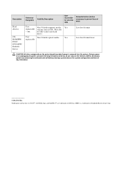
... of Dell Inc. May also - Primary power loss (unplugging the power cord and removing the battery) destroys all user data on the memory (DDR3). be SSD (solid state flash drive). Description Hard drive(s) CDROM/RW/ DVD/ DVD+RW/ Diskette Drives Reference... Designator Volatility Description User Accessible for external data Remedial Action (Action necessary to prevent loss of data) User Non Volatile magnetic media, Yes replaceable various sizes in this text: Dell™, the DELL logo, and OptiPlex...
... of Dell Inc. May also - Primary power loss (unplugging the power cord and removing the battery) destroys all user data on the memory (DDR3). be SSD (solid state flash drive). Description Hard drive(s) CDROM/RW/ DVD/ DVD+RW/ Diskette Drives Reference... Designator Volatility Description User Accessible for external data Remedial Action (Action necessary to prevent loss of data) User Non Volatile magnetic media, Yes replaceable various sizes in this text: Dell™, the DELL logo, and OptiPlex...


