Dell OptiPlex 9010 AIO Support Question
Dell OptiPlex 9010 AIO Support Question
Find answers below for this question about Dell OptiPlex 9010 AIO.Need a Dell OptiPlex 9010 AIO manual? We have 4 online manuals for this item!
Question posted by MeloKe on March 9th, 2014
Dell 9010 Aio Touch How To Remove Stand
The person who posted this question about this Dell product did not include a detailed explanation. Please use the "Request More Information" button to the right if more details would help you to answer this question.
Current Answers
Related Dell OptiPlex 9010 AIO Manual Pages
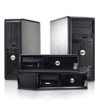
User Manual - Page 1
optical drive (optional)
7. power button 11. display 6. optical drive eject button 8. Dell Optiplex 9010
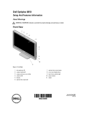
Setup And Features Information
About Warnings
WARNING: A WARNING indicates a potential for property damage, personal injury, or death. Front View
Figure 1. stand
Regulatory Model: W04C Regulatory Type: W04C001
2012 - 03 camera LED 5.
camera (optional) 3. Front View
1. ...
Owner's Manual - Page 1

Dell OptiPlex 9010 All-In-One Owner's Manual
Regulatory Model: W04C Regulatory Type: W04C001
Owner's Manual - Page 3
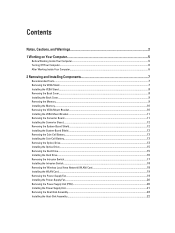
... Inside Your Computer...5 Turning Off Your Computer...6 After Working Inside Your Computer...6
2 Removing and Installing Components 7
Recommended Tools...7 Removing the VESA Stand...7 Installing the VESA Stand...8 Removing the Back Cover...8 Installing the Back Cover...9 Removing the Memory...9 Installing the Memory...10 Removing the VESA Mount Bracket...10 Installing the VESA Mount Bracket...11...
Owner's Manual - Page 4
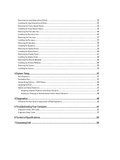
......51 Diagnostic Beep Codes...51
6 Technical Specifications...53
7 Contacting Dell ...59 Removing the Input/Output Board Shield...22 Installing the Input/Output Board Shield...25 Removing the Power-Button Board...25 Installing the Power-Button Board...26 Removing the Processor Fan...26 Installing the Processor Fan...27 Removing the Processor...27 Installing the Processor...27...
Owner's Manual - Page 5
..., first unplug the cable from your computer (see the Regulatory Compliance Homepage at www.dell.com/ regulatory_compliance
CAUTION: Many repairs may appear differently than shown in this document assumes ...by using a wrist grounding strap or by periodically touching an unpainted metal surface, such as directed by performing the removal procedure in your product documentation, or as a ...
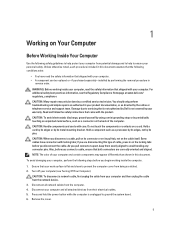
Owner's Manual - Page 6

... cables before you shut down the operating system:
- CAUTION: Before touching anything inside your computer, ground yourself by running the Dell Diagnostics.
6 In Windows 7: Click Start , then click Shut Down...Inside Your Computer
After you complete any replacement procedure, ensure you work, periodically touch an unpainted metal surface to their electrical outlets. 4. If required, verify ...
Owner's Manual - Page 7
....
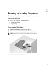
4. Lift the VESA cover upwards and away from your computer. 2
Removing and Installing Components
This section provides detailed information on a flat surface, display...flat-blade screwdriver • Phillips screwdriver • Small plastic scribe
Removing the VESA Stand
1. Place the computer on how to remove or install the components from the computer.
7
Recommended Tools
The ...
Owner's Manual - Page 8

... from the computer. Follow the procedures in After Working Inside Your Computer. 5. Follow the procedures inBefore Working Inside Your Computer. 2. Align and place the VESA stand on the computer, till it clicks into place. 4. Removing the Back Cover
1. Remove the VESA stand. 3. Remove the screws that secure the VESA stand to the computer. 3. Installing the VESA...
Owner's Manual - Page 9
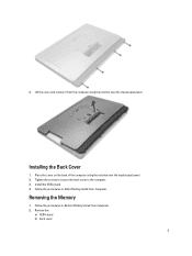
... from the computer using the notches near the input/output panel. Follow the procedures in Before Working Inside Your Computer. 2. Remove the:
a) VESA stand b) back cover
9 4. Removing the Memory
1. Install the VESA stand. 4.
Place the cover on the back of the computer using the notches near the input/output panel. 2. Installing the Back Cover...
Owner's Manual - Page 10
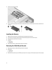
... into its connector. Pry the retention clips away from the computer.
10 Installing the Memory
1.
Remove the:
a) VESA stand b) back cover 3. Press down on the memory-card with the tab in Before Working Inside Your Computer. 2. Removing the VESA Mount Bracket
1. Lift the bracket away from the memory module until the release tabs...
Owner's Manual - Page 11

... screws that secure the converter board to the computer. 3. Tighten the screws to secure the VESA mount bracket to the computer.
Remove the:
a) VESA stand b) back cover 3. Align and place the bracket on the back of the computer. 2. Follow the procedures in After Working Inside Your Computer. Lift the convertor ...
Owner's Manual - Page 12
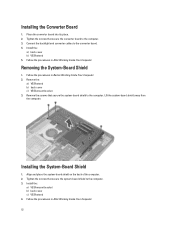
...-Board Shield
1. Follow the procedures in After Working Inside Your Computer.
12
Tighten the screws that secure the system-board shield to the computer. 3. Remove the:
a) VESA stand b) back cover c) VESA mount bracket 3. Installing the System-Board Shield
1. Tighten the screws that secure the converter board to the computer. 3. Follow the procedures...
Owner's Manual - Page 13
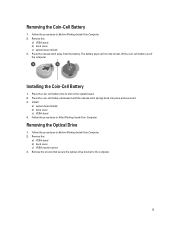
... battery. Follow the procedures in After Working Inside Your Computer. Installing the Coin-Cell Battery
1. Place the coin-cell battery into place and secures it. 3. Remove the:
a) VESA stand b) back cover c) VESA mount bracket 3. Follow the procedures in Before Working Inside Your Computer. 2.
Install:
a) system-board shield b) base cover c) VESA...
Owner's Manual - Page 15
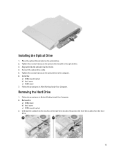
...optical drive. 3. Align and slide the optical drive into its slot. 4.
Removing the Hard Drive
1. Unthread the cables from the hard drive.
15 Connect... mount bracket b) back cover c) VESA stand 7. Follow the procedures in Before Working Inside Your Computer. 2. Follow the procedures in After Working Inside Your Computer. Remove the:
a) VESA stand b) back cover c) VESA mount bracket...
Owner's Manual - Page 19

Install:
a) system-board shield b) VESA mount bracket c) back cover d) VESA stand 5. Lift the fan bracket away from the computer.
19 Remove the:
a) VESA stand b) back cover c) VESA mount bracket d) system-board shield 3. Remove the screws that secures the fan bracket to the chassis. Tighten the screws to secure the WLAN card to it's chassis and...
Owner's Manual - Page 20

... the tab and disconnect the power-supply cable from the hooks in the computer.
20 Removing the Power Supply Unit (PSU)
1. Align and place the fan bracket on the computer...the screws to secure it 's chassis. 2. Follow the procedures in After Working Inside Your Computer. Remove the:
a) VESA stand b) back cover c) VESA mount bracket d) system-board shield e) input/output board shield f) power...
Owner's Manual - Page 31
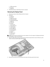
... stand b) back cover c) VESA mount bracket d) system-board shield e) input/output board shield f) WLAN card g) optical drive h) hard drive i) intrusion switch j) power-button board k) converter board l) power-supply fan m) power supply unit n) heat-sink assembly o) processor fan p) speakers q) antenna module r) system board NOTE: These instructions are valid only for non-touch computers.
Remove...
VESA Tech Sheet - Page 1
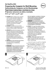
...einrichten, lesen Sie zunächst die im Lieferumfang des Computers enthaltenen Sicherheitshinweise. Die aktuellsten Informationen zu Vorschriften und Konformität finden Sie unter dell.com/regulatory_compliance. Dell OptiPlex 9010
Preparing the Computer for Wall Mounting
Vorbereitung des Computers auf die Wandmontage
Priprema računara za zidnu montažu
CAUTION: Before setting...
Statement of Volatility - Page 1
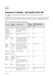
...: populated.
SPD EEPROM
SODIMM( s) - 2 present
Stores memory manufacturer data and timing information for basic boot operation, PSA
(on board Coin Cell battery. Removing the on board diags), PXE diags. Dell OptiPlex 9010 AIO
CAUTION: A CAUTION indicates either potential damage to hardware or loss of Volatility - Non-volatile (NV) components continue to retain their data immediately...
Statement of Volatility - Page 2
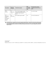
... the power cord and removing the battery) destroys all user data on the system configuration and time-ofday information.
© 2012 Dell Inc. Secondary power loss (removing the on-board coin-...
Non Volatile magnetic media, Yes
replaceable various sizes in this text: Dell™, the DELL logo, and OptiPlex™ are trademarks of Standard Microsystems Corp. Yes
replaceable
Low level ...
Similar Questions

What Motherboard And Cpu Will Be The Best Fit For The Dell Desktop Optiplex 740
(Posted by rmalone3108 2 years ago)

How Do I Turn Off The Touch Feature On Dell Optiplex
(Posted by trCla 9 years ago)

How To Disable Internal Speakers On Dell 9010 Aio
(Posted by cnimmwb 10 years ago)


How To Remove Dell Inspiron 2320 One Touch Back Stand
(Posted by zekokclnewm 10 years ago)