
Setup and Features Information Tech Sheet
Page 6
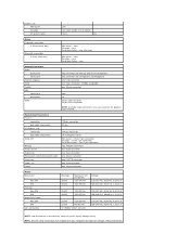
System Information Chipset Processor Video Video type: Integrated Discrete Video memory: Integrated Discrete Intel® G41 Express Chipset • Intel Core™2 Quad • Intel Core2 Duo • Intel ... 3450 up to 256 MB shared video memory (with 1 GB system memory) up to 352 MB shared video memory (with your computer, go to support.dell.com. For a complete and current listing of the specifications for your computer. Specifications NOTE: The following specifications are only those required by law to ship...
System Information Chipset Processor Video Video type: Integrated Discrete Video memory: Integrated Discrete Intel® G41 Express Chipset • Intel Core™2 Quad • Intel Core2 Duo • Intel ... 3450 up to 256 MB shared video memory (with 1 GB system memory) up to 352 MB shared video memory (with your computer, go to support.dell.com. For a complete and current listing of the specifications for your computer. Specifications NOTE: The following specifications are only those required by law to ship...
Guidebook
Page 2
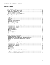
... GUIDEBOOK Table of Content THE OPTI Dell™ OptiPlex™ 380 ...3 OptiPlex 380 Technical Specifications 4 Mini Tower Computer (MT) View 4 Desktop Computer (DT) View 5 Small Form Factor Computer (SFF) View 6 Marketing System Configurations 9 Operating System...9 Chipset ...9 Processor ...10 Memory...11 Drives and Removable Storage 12 System Board Connectors 12 Graphics/Video Controller 13 External Ports/Connectors...
... GUIDEBOOK Table of Content THE OPTI Dell™ OptiPlex™ 380 ...3 OptiPlex 380 Technical Specifications 4 Mini Tower Computer (MT) View 4 Desktop Computer (DT) View 5 Small Form Factor Computer (SFF) View 6 Marketing System Configurations 9 Operating System...9 Chipset ...9 Processor ...10 Memory...11 Drives and Removable Storage 12 System Board Connectors 12 Graphics/Video Controller 13 External Ports/Connectors...
Guidebook
Page 3
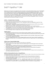
... power consumption - Optional features include Intel® Core™ 2 Quad processor, high-speed memory options, and extensive peripheral support. DELL™ OPTIPLEX™ 380 TECHNICAL GUIDEBOOK Dell™ OptiPlex™ 380 Offering more form factors and configurations than ever before in an Essential Optiplex desktop, the new Dell OptiPlex 380 is designed to help support your IT professionals throughout the technology...
... power consumption - Optional features include Intel® Core™ 2 Quad processor, high-speed memory options, and extensive peripheral support. DELL™ OPTIPLEX™ 380 TECHNICAL GUIDEBOOK Dell™ OptiPlex™ 380 Offering more form factors and configurations than ever before in an Essential Optiplex desktop, the new Dell OptiPlex 380 is designed to help support your IT professionals throughout the technology...

Guidebook
Page 7
DELL™ OPTIPLEX™ 380 TECHNICAL GUIDEBOOK 2 1 18 17 16 3 4 5 15 14 13 12 MT/DT System Board Components 1 Speaker connector (INT_SPKR) 2 Processor connector (CPU) 3 Processor power connector (12VPOWER) 4 Memory module connectors (DIMM_1) 5 Memory module connectors (DIMM_2) 6 SATA drive connectors (SATA0) 7 SATA drive connectors (SATA1) 8 SATA drive connectors (SATA2) 9 Front-panel ...
DELL™ OPTIPLEX™ 380 TECHNICAL GUIDEBOOK 2 1 18 17 16 3 4 5 15 14 13 12 MT/DT System Board Components 1 Speaker connector (INT_SPKR) 2 Processor connector (CPU) 3 Processor power connector (12VPOWER) 4 Memory module connectors (DIMM_1) 5 Memory module connectors (DIMM_2) 6 SATA drive connectors (SATA0) 7 SATA drive connectors (SATA1) 8 SATA drive connectors (SATA2) 9 Front-panel ...

Guidebook
Page 8
DELL™ OPTIPLEX™ 380 TECHNICAL GUIDEBOOK 2 1 18 17 16 15 14 13 3 4 5 6 7 12 SFF System Board Components 1 Speaker connector (INT_SPKR) 2 Processor connector (CPU) 3 Processor power connector (12VPOWER) 4 Memory module connectors (DIMM_1) 5 Memory module connectors (DIMM_2) 6 SATA drive connectors (SATA0) 7 SATA drive connectors (SATA1) 8 Front-panel connector (FRONTPANEL) 9 Power connector (...
DELL™ OPTIPLEX™ 380 TECHNICAL GUIDEBOOK 2 1 18 17 16 15 14 13 3 4 5 6 7 12 SFF System Board Components 1 Speaker connector (INT_SPKR) 2 Processor connector (CPU) 3 Processor power connector (12VPOWER) 4 Memory module connectors (DIMM_1) 5 Memory module connectors (DIMM_2) 6 SATA drive connectors (SATA0) 7 SATA drive connectors (SATA1) 8 Front-panel connector (FRONTPANEL) 9 Power connector (...

Guidebook
Page 10
...Intel® Core™ 2 Quad Q8400/2.66GHz, 4M, 1333FSB Intel® Core™ 2 Duo and Pentium® Dual Core Processors Intel® Core™ 2 Duo E8600/3.33GHz, 6M, 1333FSB Intel® Core™ 2 Duo E8500/3.16GHz, 6M, 1333FSB...; Celeron® 450/2.20GHz, 512K, 800FSB MT DT SFF X X X X X X X X X X X X X X X X X X X X X X X X X X X X X X X X X X X X X X X X X X X X X X X X X X X X X X X X X X X X 10 DELL™ OPTIPLEX™ 380 TECHNICAL GUIDEBOOK Processor NOTE: Processor numbers are not a measure of performance.
...Intel® Core™ 2 Quad Q8400/2.66GHz, 4M, 1333FSB Intel® Core™ 2 Duo and Pentium® Dual Core Processors Intel® Core™ 2 Duo E8600/3.33GHz, 6M, 1333FSB Intel® Core™ 2 Duo E8500/3.16GHz, 6M, 1333FSB...; Celeron® 450/2.20GHz, 512K, 800FSB MT DT SFF X X X X X X X X X X X X X X X X X X X X X X X X X X X X X X X X X X X X X X X X X X X X X X X X X X X X X X X X X X X X 10 DELL™ OPTIPLEX™ 380 TECHNICAL GUIDEBOOK Processor NOTE: Processor numbers are not a measure of performance.

Guidebook
Page 11
... 4GB or more of matched memory size, speed, and technology. The amount less depends on the actual system configuration. DELL™ OPTIPLEX™ 380 TECHNICAL GUIDEBOOK Memory Your computer supports a maximum of 4 GB1 of memory when you use two 2-GB DIMMs. Memory modules... should be less than 4GB. If the memory modules are not installed in matched pairs, the computer will be installed in pairs of memory requires a 64-bit enabled processor...
... 4GB or more of matched memory size, speed, and technology. The amount less depends on the actual system configuration. DELL™ OPTIPLEX™ 380 TECHNICAL GUIDEBOOK Memory Your computer supports a maximum of 4 GB1 of memory when you use two 2-GB DIMMs. Memory modules... should be less than 4GB. If the memory modules are not installed in matched pairs, the computer will be installed in pairs of memory requires a 64-bit enabled processor...
Service Manual
Page 2
...System Setup options may vary depending on your computer and may not appear in the computer. l Processor information: Displays the Processor Type, Processor Speed, Processor Bus Speed, Processor L2 cache, Processor ID, Microcode Version, Multi Core Capable and HT Capable 64-bit Technology.. l Memory information: ...is useful when you have trouble entering System Setup using this menu. Back to Contents Page System Setup Dell™ OptiPlex™ 380 Service Manual-Mini-Tower Boot Menu Navigation Keystrokes Entering System Setup System Setup Simulation System Setup Menu Options ...
...System Setup options may vary depending on your computer and may not appear in the computer. l Processor information: Displays the Processor Type, Processor Speed, Processor Bus Speed, Processor L2 cache, Processor ID, Microcode Version, Multi Core Capable and HT Capable 64-bit Technology.. l Memory information: ...is useful when you have trouble entering System Setup using this menu. Back to Contents Page System Setup Dell™ OptiPlex™ 380 Service Manual-Mini-Tower Boot Menu Navigation Keystrokes Entering System Setup System Setup Simulation System Setup Menu Options ...
Service Manual
Page 4
...the Virtual Machine Monitor (VMM) from utilizing the additional hardware capabilities provided by default. This field limits the maximum value the processor Standard CPUID Function will override and disable the integrated video controller. This option allows you to be assigned and verified. l ...Intel® SpeedStep™, enabled CPU is enabled by Intel® Trusted Execution Technology. This option enables or disables additional processor sleep states. Enable Intel® Virtualization Technology - This option is allowed to select the mode. Field specifies whether a Measured...
...the Virtual Machine Monitor (VMM) from utilizing the additional hardware capabilities provided by default. This field limits the maximum value the processor Standard CPUID Function will override and disable the integrated video controller. This option allows you to be assigned and verified. l ...Intel® SpeedStep™, enabled CPU is enabled by Intel® Trusted Execution Technology. This option enables or disables additional processor sleep states. Enable Intel® Virtualization Technology - This option is allowed to select the mode. Field specifies whether a Measured...
Service Manual
Page 5
.... You can set this option to the SATA-0 connector on the computer. Maintenance Service Tag Asset Tag SERR Messages Displays the Service Tag of the processor. Controls the SERR Message mechanism. Some graphics cards require the SERR Message mechanism be able to power up when a network interface controller receives a wake up...
.... You can set this option to the SATA-0 connector on the computer. Maintenance Service Tag Asset Tag SERR Messages Displays the Service Tag of the processor. Controls the SERR Message mechanism. Some graphics cards require the SERR Message mechanism be able to power up when a network interface controller receives a wake up...
Service Manual
Page 13
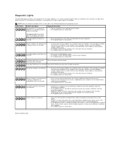
... lights are properly connected to the operating system. l If the problem persists, contact Dell. Memory modules are detected, but a memory failure has occurred. l Reseat the processor (see the Specifications section for each expansion card installed. A possible expansion card failure has...boots to the system board . If the computer malfunctions, the sequence of the same type into your computer (see Processor information for resource conflicts. Memory modules are detected, but a memory configuration or compatibility error has occurred. Suggested Resolution ...
... lights are properly connected to the operating system. l If the problem persists, contact Dell. Memory modules are detected, but a memory failure has occurred. l Reseat the processor (see the Specifications section for each expansion card installed. A possible expansion card failure has...boots to the system board . If the computer malfunctions, the sequence of the same type into your computer (see Processor information for resource conflicts. Memory modules are detected, but a memory configuration or compatibility error has occurred. Suggested Resolution ...

Service Manual
Page 27
Back to Contents Page Removing and Replacing Parts Dell™ OptiPlex™ 380 Service Manual-Mini-Tower Cover Coin-Cell Battery Optical Drive Video Card Hard Drive Power Supply System Board Drive Bezel Memory Module Fan I/O Panel Heat Sink Processor Back to Contents Page
Back to Contents Page Removing and Replacing Parts Dell™ OptiPlex™ 380 Service Manual-Mini-Tower Cover Coin-Cell Battery Optical Drive Video Card Hard Drive Power Supply System Board Drive Bezel Memory Module Fan I/O Panel Heat Sink Processor Back to Contents Page

Service Manual
Page 31
4. Disconnect the optical-drive power cable from the system board. Disconnect the processor power cable from the optical drive. 5.
4. Disconnect the optical-drive power cable from the system board. Disconnect the processor power cable from the optical drive. 5.

Service Manual
Page 35
Back to release the processor cover. 3. Pull the processor cover release lever down and out to Contents Page Processor Dell™ OptiPlex™ 380 Service Manual-Mini-Tower WARNING: Before working inside your computer, read the safety information that shipped with your computer. Removing the Processor 1. For additional safety best practices information, see the Regulatory Compliance Homepage at www.dell.com/regulatory_compliance. Follow the procedures in Before Working Inside Your Computer. 2. Lift the processor cover.
Back to release the processor cover. 3. Pull the processor cover release lever down and out to Contents Page Processor Dell™ OptiPlex™ 380 Service Manual-Mini-Tower WARNING: Before working inside your computer, read the safety information that shipped with your computer. Removing the Processor 1. For additional safety best practices information, see the Regulatory Compliance Homepage at www.dell.com/regulatory_compliance. Follow the procedures in Before Working Inside Your Computer. 2. Lift the processor cover.

Service Manual
Page 36
Replacing the Processor To replace the processor, perform the above steps in the socket. CAUTION: When replacing the processor, do not touch any of the pins inside the socket or allow any objects to Contents Page Back to fall on the system board. Remove the processor from its socket on the pins in reverse order. 4.
Replacing the Processor To replace the processor, perform the above steps in the socket. CAUTION: When replacing the processor, do not touch any of the pins inside the socket or allow any objects to Contents Page Back to fall on the system board. Remove the processor from its socket on the pins in reverse order. 4.
Service Manual
Page 37
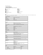
...;2 Quad, Core2 Duo, Intel Pentium® Dual-Core, Intel Celeron® Dual-Core, Intel Celeron 512 KB - 12 MB (depending on processor model) Memory Type Speed Connectors Capacity Minimum memory Maximum memory DDR3 SDRAM (non-ECC memory only) 1067 MHz two 1 GB or 2 GB ...Start® Help and Support and select the option to Contents Page Specifications Dell™ OptiPlex™ 380 Service Manual-Mini-Tower System Information Memory Audio Expansion Bus Drives System Board Connectors Physical Processor Video Network Cards External Connectors Power Environmental NOTE: Offerings may vary by ...
...;2 Quad, Core2 Duo, Intel Pentium® Dual-Core, Intel Celeron® Dual-Core, Intel Celeron 512 KB - 12 MB (depending on processor model) Memory Type Speed Connectors Capacity Minimum memory Maximum memory DDR3 SDRAM (non-ECC memory only) 1067 MHz two 1 GB or 2 GB ...Start® Help and Support and select the option to Contents Page Specifications Dell™ OptiPlex™ 380 Service Manual-Mini-Tower System Information Memory Audio Expansion Bus Drives System Board Connectors Physical Processor Video Network Cards External Connectors Power Environmental NOTE: Offerings may vary by ...
Service Manual
Page 38
... form factor - System Board Connectors PCI 2.3: connectors data width (maximum) PCI Express x16: connectors data width (maximum) Serial ATA Memory Processor fan System fan Front panel control/front panel audio Processor Power 12V Power 120-pin connector 32 bits 164-pin connector 16 PCI-Express lanes Mini-tower - Express x1): Mini-tower...
... form factor - System Board Connectors PCI 2.3: connectors data width (maximum) PCI Express x16: connectors data width (maximum) Serial ATA Memory Processor fan System fan Front panel control/front panel audio Processor Power 12V Power 120-pin connector 32 bits 164-pin connector 16 PCI-Express lanes Mini-tower - Express x1): Mini-tower...

Service Manual
Page 41
... Board 1. For additional safety best practices information, see the Regulatory Compliance Homepage at www.dell.com/regulatory_compliance. Remove the memory. 3. Disconnect the processor power cable from the system board. 6. Back to Contents Page System Board Dell™ OptiPlex™ 380 Service Manual-Mini-Tower WARNING: Before working inside your computer, read the safety information that...
... Board 1. For additional safety best practices information, see the Regulatory Compliance Homepage at www.dell.com/regulatory_compliance. Remove the memory. 3. Disconnect the processor power cable from the system board. 6. Back to Contents Page System Board Dell™ OptiPlex™ 380 Service Manual-Mini-Tower WARNING: Before working inside your computer, read the safety information that...
Service Manual
Page 53
...The procedures in this type of cable, press in Working on Your Computer. Back to Contents Page Working on Your Computer Dell™ OptiPlex™ 380 Service Manual-Mini-Tower Before Working Inside Your Computer Recommended Tools Turning Off Your Computer After Working Inside Your Computer Before Working ...: To avoid electrostatic discharge, ground yourself by using a wrist grounding strap or by periodically touching an unpainted metal surface, such as a processor by its edges, not by its pins. Do not touch the components or contacts on the cable itself. Some cables have performed the ...
...The procedures in this type of cable, press in Working on Your Computer. Back to Contents Page Working on Your Computer Dell™ OptiPlex™ 380 Service Manual-Mini-Tower Before Working Inside Your Computer Recommended Tools Turning Off Your Computer After Working Inside Your Computer Before Working ...: To avoid electrostatic discharge, ground yourself by using a wrist grounding strap or by periodically touching an unpainted metal surface, such as a processor by its edges, not by its pins. Do not touch the components or contacts on the cable itself. Some cables have performed the ...


