Owner's Manual
Page 3
... Inside Your Computer...7 2 Removing and Installing Components 9 System Overview...9 Inside view ...9 Removing the Stand Cover...10 Installing the Stand Cover...10 Removing the VESA Stand...10 Installing the VESA Stand...11 Removing the Back Cover...11 Installing the Back Cover...13 Removing the Optical Disk Drive...13 Installing the Optical Disk Drive...
... Inside Your Computer...7 2 Removing and Installing Components 9 System Overview...9 Inside view ...9 Removing the Stand Cover...10 Installing the Stand Cover...10 Removing the VESA Stand...10 Installing the VESA Stand...11 Removing the Back Cover...11 Installing the Back Cover...13 Removing the Optical Disk Drive...13 Installing the Optical Disk Drive...
Owner's Manual
Page 10
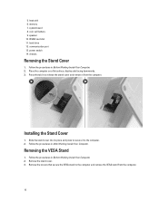
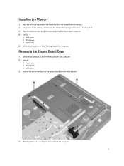
memory 7. Press the tab in After Working Inside Your Computer. Remove the screws that secure the VESA stand to the computer. 2. WLAN card slot 11. hard drive 12. communication port 13. Follow the procedures in Before Working Inside Your Computer. 2. Place the ... 8. power switch 14. Installing the Stand Cover 1. Follow the procedures in to release the stand cover and remove it to the computer and remove the VESA stand from the computer. coin-cell battery 9. chassis Removing the Stand Cover 1. Remove the stand cover. 3. Removing the...
memory 7. Press the tab in After Working Inside Your Computer. Remove the screws that secure the VESA stand to the computer. 2. WLAN card slot 11. hard drive 12. communication port 13. Follow the procedures in Before Working Inside Your Computer. 2. Place the ... 8. power switch 14. Installing the Stand Cover 1. Follow the procedures in to release the stand cover and remove it to the computer and remove the VESA stand from the computer. coin-cell battery 9. chassis Removing the Stand Cover 1. Remove the stand cover. 3. Removing the...
Owner's Manual
Page 11
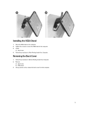
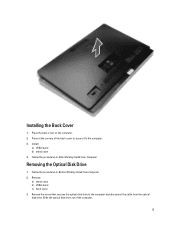
Place the VESA stand on the computer. 2. Tighten the screws to secure the VESA stand to the computer. 3. Follow the procedures in Before Working Inside Your Computer. 2. Removing the Back Cover 1. Follow the procedures in After Working Inside Your Computer. Remove: a) stand cover b) VESA stand 3. Install: a) stand cover 4. Using a plastic scribe, release the back cover from the computer. 11 Installing the VESA Stand 1.
Place the VESA stand on the computer. 2. Tighten the screws to secure the VESA stand to the computer. 3. Follow the procedures in Before Working Inside Your Computer. 2. Removing the Back Cover 1. Follow the procedures in After Working Inside Your Computer. Remove: a) stand cover b) VESA stand 3. Install: a) stand cover 4. Using a plastic scribe, release the back cover from the computer. 11 Installing the VESA Stand 1.
Owner's Manual
Page 13
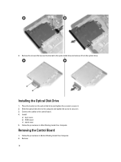
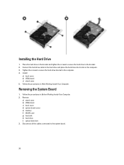
Follow the procedures in Before Working Inside Your Computer. 2. Slide the optical disk drive out of the back cover to secure it to the computer and disconnect the cable from the optical disk drive. Remove: a) stand cover b) VESA stand c) back cover 3. Remove the screw that secures the optical disk drive to the computer. 3. Install: a) VESA stand b) stand cover 4. Press at the corners of the computer. 13 Installing the Back Cover 1. Removing the Optical Disk Drive 1. Place the back cover on the computer. 2. Follow the procedures in After Working Inside Your Computer.
Follow the procedures in Before Working Inside Your Computer. 2. Slide the optical disk drive out of the back cover to secure it to the computer and disconnect the cable from the optical disk drive. Remove: a) stand cover b) VESA stand c) back cover 3. Remove the screw that secures the optical disk drive to the computer. 3. Install: a) VESA stand b) stand cover 4. Press at the corners of the computer. 13 Installing the Back Cover 1. Removing the Optical Disk Drive 1. Place the back cover on the computer. 2. Follow the procedures in After Working Inside Your Computer.
Owner's Manual
Page 14
... secure it from the optical drive. Place the bracket on the optical disk drive and tighten the screws to the control board. 4. Install: a) back cover b) VESA stand c) stand cover 5. Follow the procedures in After Working Inside Your Computer. 4.
... secure it from the optical drive. Place the bracket on the optical disk drive and tighten the screws to the control board. 4. Install: a) back cover b) VESA stand c) stand cover 5. Follow the procedures in After Working Inside Your Computer. 4.
Owner's Manual
Page 15
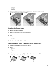
... board from the computer. 15 Disconnect the cables from the WLAN card. Connect the cables to the computer. Install: a) back cover b) VESA stand c) stand cover 5. Disconnect the antenna cables from the control board and remove the screws that secures the WLAN card to the computer.... the screw that secure the control board to the control board. 4. Follow the procedures in After Working Inside Your Computer. a) stand cover b) VESA stand c) back cover 3. Installing the Control Board 1. Place the control board on the computer. 2. Tighten the screws to secure the control board...
... board from the computer. 15 Disconnect the cables from the WLAN card. Connect the cables to the computer. Install: a) back cover b) VESA stand c) stand cover 5. Disconnect the antenna cables from the control board and remove the screws that secures the WLAN card to the computer.... the screw that secure the control board to the control board. 4. Follow the procedures in After Working Inside Your Computer. a) stand cover b) VESA stand c) back cover 3. Installing the Control Board 1. Place the control board on the computer. 2. Tighten the screws to secure the control board...
Owner's Manual
Page 16
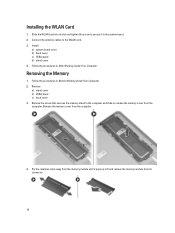
Slide the WLAN card into its connector. 16 Install: a) system board cover b) back cover c) VESA stand d) stand cover 4. Removing the Memory 1. Follow the procedures in After Working Inside Your Computer. Remove the memory cover from the computer. Follow the ... Working Inside Your Computer. 2. Remove the screw that secures the memory stand to the computer and slide to the system board. 2. Remove: a) stand cover b) VESA stand c) back cover 3. Lift and remove the memory module from the memory module until it to release the memory cover from the computer. 4. Connect the...
Slide the WLAN card into its connector. 16 Install: a) system board cover b) back cover c) VESA stand d) stand cover 4. Removing the Memory 1. Follow the procedures in After Working Inside Your Computer. Remove the memory cover from the computer. Follow the ... Working Inside Your Computer. 2. Remove the screw that secures the memory stand to the computer and slide to the system board. 2. Remove: a) stand cover b) VESA stand c) back cover 3. Lift and remove the memory module from the memory module until it to release the memory cover from the computer. 4. Connect the...
Owner's Manual
Page 17
...Your Computer. Place the memory cover back into its place and tighten the screw to remove it . 4. Removing the System Board Cover 1. Remove: a) stand cover b) VESA stand c) back cover 3. Lift the system board cover up to secure it from the computer. 17 Installing the Memory 1. Install: a) back cover... b) VESA stand c) stand cover 5. Remove the screw that secures the system board cover to secure them in the system-board connector. 2. Press down on the ...
...Your Computer. Place the memory cover back into its place and tighten the screw to remove it . 4. Removing the System Board Cover 1. Remove: a) stand cover b) VESA stand c) back cover 3. Lift the system board cover up to secure it from the computer. 17 Installing the Memory 1. Install: a) back cover... b) VESA stand c) stand cover 5. Remove the screw that secures the system board cover to secure them in the system-board connector. 2. Press down on the ...
Owner's Manual
Page 18
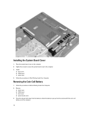
Install: a) back cover b) VESA stand c) stand cover 4. Follow the procedures in After Working Inside Your Computer. Tighten the screws to secure the system board cover to pop up from ... the battery to the computer. 3. Place the system board cover on the computer. 2. Follow the procedures in Before Working Inside Your Computer. 2. Remove: a) stand cover b) VESA stand c) back cover d) system board cover 3. Installing the System Board Cover 1.
Install: a) back cover b) VESA stand c) stand cover 4. Follow the procedures in After Working Inside Your Computer. Tighten the screws to secure the system board cover to pop up from ... the battery to the computer. 3. Place the system board cover on the computer. 2. Follow the procedures in Before Working Inside Your Computer. 2. Remove: a) stand cover b) VESA stand c) back cover d) system board cover 3. Installing the System Board Cover 1.
Owner's Manual
Page 19
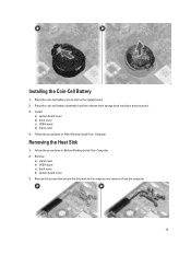
Follow the procedures in Before Working Inside Your Computer. 2. Install: a) system board cover b) back cover c) VESA stand d) stand cover 4. Follow the procedures in After Working Inside Your Computer. Remove: a) stand cover b) VESA stand c) back cover d) system board cover 3. Press the coin-cell battery downward until the release latch springs back into its slot...
Follow the procedures in Before Working Inside Your Computer. 2. Install: a) system board cover b) back cover c) VESA stand d) stand cover 4. Follow the procedures in After Working Inside Your Computer. Remove: a) stand cover b) VESA stand c) back cover d) system board cover 3. Press the coin-cell battery downward until the release latch springs back into its slot...
Owner's Manual
Page 20
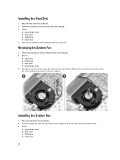
... the computer. Place the system fan on the computer and connect the cable to the system board. 3. Install: a) system board cover b) back cover c) VESA stand d) stand cover 20 Installing the System Fan 1. Remove the screws that secure the system fan to the computer. 3. Remove: a) stand cover... b) VESA stand c) back cover d) system board cover 3. Tighten the screws to secure the heat sink to the computer and remove it from the system board...
... the computer. Place the system fan on the computer and connect the cable to the system board. 3. Install: a) system board cover b) back cover c) VESA stand d) stand cover 20 Installing the System Fan 1. Remove the screws that secure the system fan to the computer. 3. Remove: a) stand cover... b) VESA stand c) back cover d) system board cover 3. Tighten the screws to secure the heat sink to the computer and remove it from the system board...
Owner's Manual
Page 21
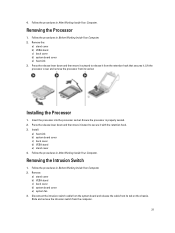
...and then move it outward to secure it . Follow the procedures in Before Working Inside Your Computer. 2. Remove: a) stand cover b) VESA stand c) back cover d) system board cover e) system fan 3. Follow the procedures in Before Working Inside Your Computer. 2. Ensure the ...Working Inside Your Computer. Lift the processor cover and remove the processor from its socket. Removing the Processor 1. Remove the: a) stand cover b) VESA stand c) back cover d) system board cover e) heat sink 3. Insert the processor into the processor socket. 4. Installing the Processor 1. Install:...
...and then move it outward to secure it . Follow the procedures in Before Working Inside Your Computer. 2. Remove: a) stand cover b) VESA stand c) back cover d) system board cover e) system fan 3. Follow the procedures in Before Working Inside Your Computer. 2. Ensure the ...Working Inside Your Computer. Lift the processor cover and remove the processor from its socket. Removing the Processor 1. Remove the: a) stand cover b) VESA stand c) back cover d) system board cover e) heat sink 3. Insert the processor into the processor socket. 4. Installing the Processor 1. Install:...
Owner's Manual
Page 22
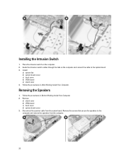
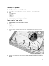
Disconnect the speaker cable from the computer. 22 Install: a) system fan b) system board cover c) back cover d) VESA stand e) stand cover 4. Remove the screws that secure the speakers to the system board. 3. Guide the intrusion-switch cables through... the tabs on the computer. 2. Follow the procedures in Before Working Inside Your Computer. 2. Remove: a) stand cover b) VESA stand c) back cover d) system board cover 3. Follow the procedures in After Working Inside Your Computer. Removing the Speakers 1. Installing the Intrusion Switch 1. ...
Disconnect the speaker cable from the computer. 22 Install: a) system fan b) system board cover c) back cover d) VESA stand e) stand cover 4. Remove the screws that secure the speakers to the system board. 3. Guide the intrusion-switch cables through... the tabs on the computer. 2. Follow the procedures in Before Working Inside Your Computer. 2. Remove: a) stand cover b) VESA stand c) back cover d) system board cover 3. Follow the procedures in After Working Inside Your Computer. Removing the Speakers 1. Installing the Intrusion Switch 1. ...
Owner's Manual
Page 23
... cables through the tabs on the chassis. 4. Follow the procedures in After Working Inside Your Computer. Remove: a) stand cover b) VESA stand c) back cover d) system board cover 3. Install: a) system board cover b) back cover c) VESA stand d) stand cover 4. Release the power-switch cable from its tabs on the computer and connect the cable to...
... cables through the tabs on the chassis. 4. Follow the procedures in After Working Inside Your Computer. Remove: a) stand cover b) VESA stand c) back cover d) system board cover 3. Install: a) system board cover b) back cover c) VESA stand d) stand cover 4. Release the power-switch cable from its tabs on the computer and connect the cable to...
Owner's Manual
Page 24
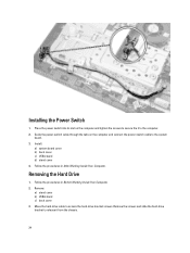
... the Power Switch 1. Remove the screws and slide the hard-drive bracket to release it to the system board. 3. Remove: a) stand cover b) VESA stand c) back cover 3. Place the power switch into its slot on the computer and connect the power-switch cable to the computer. 2. Install: ...a) system board cover b) back cover c) VESA stand d) stand cover 4. Removing the Hard Drive 1. Guide the power-switch cable through the tabs on the computer and tighten the screws to ...
... the Power Switch 1. Remove the screws and slide the hard-drive bracket to release it to the system board. 3. Remove: a) stand cover b) VESA stand c) back cover 3. Place the power switch into its slot on the computer and connect the power-switch cable to the computer. 2. Install: ...a) system board cover b) back cover c) VESA stand d) stand cover 4. Removing the Hard Drive 1. Guide the power-switch cable through the tabs on the computer and tighten the screws to ...
Owner's Manual
Page 26
... c) stand cover 5. Remove: a) stand cover b) VESA stand c) back cover d) system board cover e) memory f) WLAN card g) heat sink h) hard drive i) optical disk drive 3. Connect the hard-drive cable to the computer. 4. Tighten ...
... c) stand cover 5. Remove: a) stand cover b) VESA stand c) back cover d) system board cover e) memory f) WLAN card g) heat sink h) hard drive i) optical disk drive 3. Connect the hard-drive cable to the computer. 4. Tighten ...
Owner's Manual
Page 31
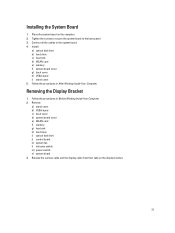
Remove: a) stand cover b) VESA stand c) back cover d) system board cover e) WLAN card f) memory g) heat sink h) hard drive i) optical disk drive j) control board k) system fan l) intrusion switch m) power switch n) system ... the display cable from their tabs on the computer. 2. Install: a) optical disk drive b) hard drive c) heat sink d) WLAN card e) memory f) system board cover g) back cover h) VESA stand i) stand cover 5. Removing the Display Bracket 1. Place the system board on the display bracket. 31 Connect all the cables to the base panel. 3. Installing...
Remove: a) stand cover b) VESA stand c) back cover d) system board cover e) WLAN card f) memory g) heat sink h) hard drive i) optical disk drive j) control board k) system fan l) intrusion switch m) power switch n) system ... the display cable from their tabs on the computer. 2. Install: a) optical disk drive b) hard drive c) heat sink d) WLAN card e) memory f) system board cover g) back cover h) VESA stand i) stand cover 5. Removing the Display Bracket 1. Place the system board on the display bracket. 31 Connect all the cables to the base panel. 3. Installing...
Owner's Manual
Page 35
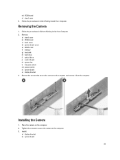
Remove the screws that secure the camera to the computer. 3. Remove: a) stand cover b) VESA stand c) back cover d) system board cover e) WLAN card f) memory g) heat sink h) hard drive i) optical drive j) control board k) system fan l) intrusion switch m) power switch ...it from the computer. Installing the Camera 1. Place the camera on the computer. 2. Install: a) display bracket b) system board 35 Removing the Camera 1. m) VESA stand n) stand cover 5. Follow the procedures in After Working Inside Your Computer. Follow the procedures in Before Working Inside Your Computer. 2.
Remove the screws that secure the camera to the computer. 3. Remove: a) stand cover b) VESA stand c) back cover d) system board cover e) WLAN card f) memory g) heat sink h) hard drive i) optical drive j) control board k) system fan l) intrusion switch m) power switch ...it from the computer. Installing the Camera 1. Place the camera on the computer. 2. Install: a) display bracket b) system board 35 Removing the Camera 1. m) VESA stand n) stand cover 5. Follow the procedures in After Working Inside Your Computer. Follow the procedures in Before Working Inside Your Computer. 2.
Owner's Manual
Page 36
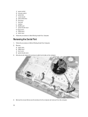
... the computer. 4. c) power switch d) intrusion switch e) system fan f) control board g) optical disk drive h) hard drive i) heat sink j) memory k) WLAN card l) system board cover m) back cover n) VESA stand o) stand cover 4. Removing the Serial Port 1. Disconnect and release the serial-port cable from the computer. 36 Follow the procedures in After Working Inside...
... the computer. 4. c) power switch d) intrusion switch e) system fan f) control board g) optical disk drive h) hard drive i) heat sink j) memory k) WLAN card l) system board cover m) back cover n) VESA stand o) stand cover 4. Removing the Serial Port 1. Disconnect and release the serial-port cable from the computer. 36 Follow the procedures in After Working Inside...
Owner's Manual
Page 37
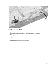
Installing the Serial Port 1. Follow the procedures in After Working Inside Your Computer. 37 Install: a) system board cover b) back cover c) VESA stand d) stand cover 4. Tighten the screws to secure the serial port to the system board. 3. Guide the serial-port cable through its tabs on the computer and connect it to the computer. 2.
Installing the Serial Port 1. Follow the procedures in After Working Inside Your Computer. 37 Install: a) system board cover b) back cover c) VESA stand d) stand cover 4. Tighten the screws to secure the serial port to the system board. 3. Guide the serial-port cable through its tabs on the computer and connect it to the computer. 2.


