Owner's Manual
Page 4
Installing the Power Switch...24 Removing the Hard Drive...24 Installing the Hard Drive...26 Removing the System Board...26 System Board Components...30 Installing the System Board...31 Removing the Display Bracket...31 Installing the Display Bracket...34 ...-Boot System Assessment (ePSA) Diagnostics 51 5 Troubleshooting Your Computer 53 Diagnostic Power LED Codes...53 Beep Codes...54 Error Messages...54 6 Technical Specifications...57 7 Contacting Dell...63
Installing the Power Switch...24 Removing the Hard Drive...24 Installing the Hard Drive...26 Removing the System Board...26 System Board Components...30 Installing the System Board...31 Removing the Display Bracket...31 Installing the Display Bracket...34 ...-Boot System Assessment (ePSA) Diagnostics 51 5 Troubleshooting Your Computer 53 Diagnostic Power LED Codes...53 Beep Codes...54 Error Messages...54 6 Technical Specifications...57 7 Contacting Dell...63
Owner's Manual
Page 10
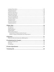
... remove it to the computer. 2. heat sink 6. Press the tab in Before Working Inside Your Computer. 2. Follow the procedures in After Working Inside Your Computer. hard drive 12. Follow the procedures in Before Working Inside Your Computer. 2. coin-cell battery 9. communication port 13. Installing the Stand Cover 1. Remove the stand cover. 3. Slide...
... remove it to the computer. 2. heat sink 6. Press the tab in Before Working Inside Your Computer. 2. Follow the procedures in After Working Inside Your Computer. hard drive 12. Follow the procedures in Before Working Inside Your Computer. 2. coin-cell battery 9. communication port 13. Installing the Stand Cover 1. Remove the stand cover. 3. Slide...
Owner's Manual
Page 24
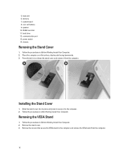
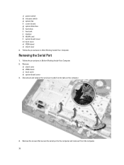
... to release it to the system board. 3. Follow the procedures in After Working Inside Your Computer. Remove the screws and slide the hard-drive bracket to access the hard-drive bracket screws. Installing the Power Switch 1. Follow the procedures in Before Working Inside Your Computer. 2. Guide the power-switch cable through the tabs on...
... to release it to the system board. 3. Follow the procedures in After Working Inside Your Computer. Remove the screws and slide the hard-drive bracket to access the hard-drive bracket screws. Installing the Power Switch 1. Follow the procedures in Before Working Inside Your Computer. 2. Guide the power-switch cable through the tabs on...
Owner's Manual
Page 25
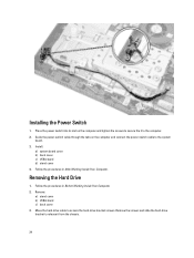
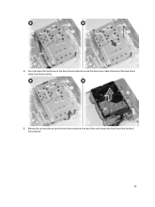
Turn and place the hard drive on the hard-drive bracket to the hard drive and remove the hard drive from the hard drive. 5. 4. Disconnect the hard-drive cable from the harddrive bracket. 25 Remove the screws that secure the hard-drive bracket to access the hard-drive cable.
Turn and place the hard drive on the hard-drive bracket to the hard drive and remove the hard drive from the hard drive. 5. 4. Disconnect the hard-drive cable from the harddrive bracket. 25 Remove the screws that secure the hard-drive bracket to access the hard-drive cable.
Owner's Manual
Page 26
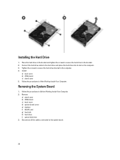
...Disconnect all the cables connected to the hard drive and place the hard drive into its slot on the computer. 3. Connect the hard-drive cable to the system board. 26 Follow the procedures in the bracket and tighten the screws to secure the hard drive to the computer. 4. Remove: a)... stand cover b) VESA stand c) back cover d) system board cover e) memory f) WLAN card g) heat sink h) hard drive i) optical disk drive 3. Installing the Hard Drive 1. Follow the procedures in After Working Inside Your...
...Disconnect all the cables connected to the hard drive and place the hard drive into its slot on the computer. 3. Connect the hard-drive cable to the system board. 26 Follow the procedures in the bracket and tighten the screws to secure the hard drive to the computer. 4. Remove: a)... stand cover b) VESA stand c) back cover d) system board cover e) memory f) WLAN card g) heat sink h) hard drive i) optical disk drive 3. Installing the Hard Drive 1. Follow the procedures in After Working Inside Your...
Owner's Manual
Page 30
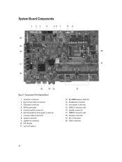
... (2) 16. speaker connector 17. USB 2.0 connectors (4) 18. SATA connectors 5. headphone connector 14. Components Of The System Board 1. LVDS connector 30 SO-DIMM memory slots (2) 13. hard drive/optical drive power connector 7. system fan connector 10. converter board connector 8. intrusion switch connector 6. DC-in Connector 20. System Board Components Figure 1.
... (2) 16. speaker connector 17. USB 2.0 connectors (4) 18. SATA connectors 5. headphone connector 14. Components Of The System Board 1. LVDS connector 30 SO-DIMM memory slots (2) 13. hard drive/optical drive power connector 7. system fan connector 10. converter board connector 8. intrusion switch connector 6. DC-in Connector 20. System Board Components Figure 1.
Owner's Manual
Page 31
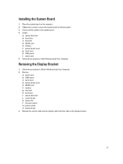
...Your Computer. 2. Remove: a) stand cover b) VESA stand c) back cover d) system board cover e) WLAN card f) memory g) heat sink h) hard drive i) optical disk drive j) control board k) system fan l) intrusion switch m) power switch n) system board 3. Connect all the cables to the base panel. 3. Follow... the procedures in After Working Inside Your Computer. Installing the System Board 1. Install: a) optical disk drive b) hard drive c) heat sink d) WLAN card e) memory f) system board cover g) back cover h) VESA stand i) stand cover 5. Release the camera cable...
...Your Computer. 2. Remove: a) stand cover b) VESA stand c) back cover d) system board cover e) WLAN card f) memory g) heat sink h) hard drive i) optical disk drive j) control board k) system fan l) intrusion switch m) power switch n) system board 3. Connect all the cables to the base panel. 3. Follow... the procedures in After Working Inside Your Computer. Installing the System Board 1. Install: a) optical disk drive b) hard drive c) heat sink d) WLAN card e) memory f) system board cover g) back cover h) VESA stand i) stand cover 5. Release the camera cable...
Owner's Manual
Page 34
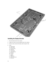
Tighten the screws to secure the display bracket to the computer. 3. Installing the Display Bracket 1. Place the display bracket on the computer. 2. Install: a) system board b) power switch c) intrusion switch d) system fan e) control board f) optical disk drive g) hard drive h) heat sink i) memory j) WLAN card k) system board cover l) back cover 34 Guide the camera cable and the display cable through their tabs. 4.
Tighten the screws to secure the display bracket to the computer. 3. Installing the Display Bracket 1. Place the display bracket on the computer. 2. Install: a) system board b) power switch c) intrusion switch d) system fan e) control board f) optical disk drive g) hard drive h) heat sink i) memory j) WLAN card k) system board cover l) back cover 34 Guide the camera cable and the display cable through their tabs. 4.
Owner's Manual
Page 35
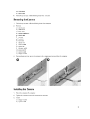
Remove: a) stand cover b) VESA stand c) back cover d) system board cover e) WLAN card f) memory g) heat sink h) hard drive i) optical drive j) control board k) system fan l) intrusion switch m) power switch n) system board o) display bracket 3. Remove the screws that secure the camera to the computer. 3. Installing the Camera 1. ...
Remove: a) stand cover b) VESA stand c) back cover d) system board cover e) WLAN card f) memory g) heat sink h) hard drive i) optical drive j) control board k) system fan l) intrusion switch m) power switch n) system board o) display bracket 3. Remove the screws that secure the camera to the computer. 3. Installing the Camera 1. ...
Owner's Manual
Page 36
c) power switch d) intrusion switch e) system fan f) control board g) optical disk drive h) hard drive i) heat sink j) memory k) WLAN card l) system board cover m) back cover n) VESA stand o) stand cover 4. Remove: a) stand cover b) VESA stand c) back cover d) system board cover 3. Disconnect ...
c) power switch d) intrusion switch e) system fan f) control board g) optical disk drive h) hard drive i) heat sink j) memory k) WLAN card l) system board cover m) back cover n) VESA stand o) stand cover 4. Remove: a) stand cover b) VESA stand c) back cover d) system board cover 3. Disconnect ...
Owner's Manual
Page 39
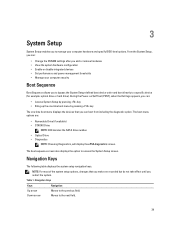
... performance and power management thresholds • Manage your computer hardware and specify BIOS‐level options. During the Power-on Self Test (POST), when the Dell logo appears, you can: • Access System Setup by pressing key • Bring up the one-time boot menu by pressing key The one-time... Boot Sequence Boot Sequence allows you to bypass the System Setup‐defined boot device order and boot directly to a specific device (for example: optical drive or hard drive).
... performance and power management thresholds • Manage your computer hardware and specify BIOS‐level options. During the Power-on Self Test (POST), when the Dell logo appears, you can: • Access System Setup by pressing key • Bring up the one-time boot menu by pressing key The one-time... Boot Sequence Boot Sequence allows you to bypass the System Setup‐defined boot device order and boot directly to a specific device (for example: optical drive or hard drive).
Owner's Manual
Page 41
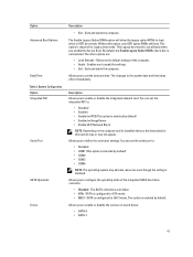
...default, the Enable Legacy Option ROMs check-box is selected by default) • Enabled w/ImageServer • Enable UEFI Network Stack NOTE: Depending on -board drives: • SATA-0 • SATA-1 41 Allows you to apply the settings. • Exit - You can set the integrated NIC to: •...mode of the computer. • Apply - The other options are hidden. • ATA - Restores the default settings of the integrated SATA hard drive controller. • Disabled - Allows you to the system date and time takes effect immediately. This option is required for Legacy boot mode....
...default, the Enable Legacy Option ROMs check-box is selected by default) • Enabled w/ImageServer • Enable UEFI Network Stack NOTE: Depending on -board drives: • SATA-0 • SATA-1 41 Allows you to apply the settings. • Exit - You can set the integrated NIC to: •...mode of the computer. • Apply - The other options are hidden. • ATA - Restores the default settings of the integrated SATA hard drive controller. • Disabled - Allows you to the system date and time takes effect immediately. This option is required for Legacy boot mode....
Owner's Manual
Page 42
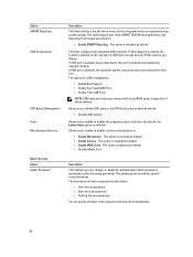
Security Option Admin Password Description This field controls if the hard drive errors for the integrated drives are enabled by default. • Disable OSD buttons Allows you to disable OSD buttons, the OSD buttons are reported during system ... disable the integrated audio controllers. The admin password enables several security features. The options for operation system. This option is selected by default. The drive does not have a password set , change, or delete the administrator (admin) password (sometimes called the setup password). If Boot Support is enabled...
Security Option Admin Password Description This field controls if the hard drive errors for the integrated drives are enabled by default. • Disable OSD buttons Allows you to disable OSD buttons, the OSD buttons are reported during system ... disable the integrated audio controllers. The admin password enables several security features. The options for operation system. This option is selected by default. The drive does not have a password set , change, or delete the administrator (admin) password (sometimes called the setup password). If Boot Support is enabled...
Owner's Manual
Page 43
... disable the BIOS module interface of characters allowed for the system and internal HDD passwords when powered on the computer's internal hard disk drive (HDD). Allows you to bypass the System Password and the internal HDD password prompts during a system restart. • Disabled - The... Min • Admin Password Max • System Password Min • System Password Max Allows you to determine whether changes to the system and hard disk passwords are set . • Allow Non-Admin Password Changes - You cannot set an admin password if a system password or an HDD password...
... disable the BIOS module interface of characters allowed for the system and internal HDD passwords when powered on the computer's internal hard disk drive (HDD). Allows you to bypass the System Password and the internal HDD password prompts during a system restart. • Disabled - The... Min • Admin Password Max • System Password Min • System Password Max Allows you to determine whether changes to the system and hard disk passwords are set . • Allow Non-Admin Password Changes - You cannot set an admin password if a system password or an HDD password...
Owner's Manual
Page 54
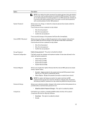
... configuration. System fan failure Possible fan failure CPU fan failure Possible CPU fan failure Hard-disk drive failure Possible hard drive failure during boot test. No boot device available No bootable partition on the hard drive, a cable or connector is reset, BIOS Setup default has been loaded. The... computer failed to run the setup utility. The memory may be compatible. For help in resolving this problem, please note this system have failed at booting this checkpoint and contact Dell ...
... configuration. System fan failure Possible fan failure CPU fan failure Possible CPU fan failure Hard-disk drive failure Possible hard drive failure during boot test. No boot device available No bootable partition on the hard drive, a cable or connector is reset, BIOS Setup default has been loaded. The... computer failed to run the setup utility. The memory may be compatible. For help in resolving this problem, please note this system have failed at booting this checkpoint and contact Dell ...
Owner's Manual
Page 55
... the device has two USB cables, connect both of range may or may not indicate a potential hard drive problem 55 Use an external power source to a Drive SELF support technician. USB over current error Disconnect the USB device. Dell recommends that a parameter has exceeded its normal operating range. MONITORING SYSTEM has reported that you...
... the device has two USB cables, connect both of range may or may not indicate a potential hard drive problem 55 Use an external power source to a Drive SELF support technician. USB over current error Disconnect the USB device. Dell recommends that a parameter has exceeded its normal operating range. MONITORING SYSTEM has reported that you...
Owner's Manual
Page 58
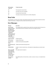
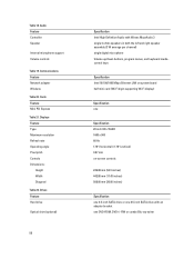
Drives Feature Hard drive Optical drive (optional) 58 Specification Intel High Definition Audio with Waves MazzAudio 3 single 4-ohms speakers in both the left and right speaker assembly (3 W average per channel) single ...-screen controls 249.08 mm (9.81 inches) 442.80 mm (17.43 inches) 508.00 mm (20.00 inches) Specification one 3.5-inch SATA drive or one 2.5-inch SATA drive with an adapter bracket one DVD-ROM, DVD+/- RW or combo Blu-ray writer Communications Feature Network adapter Wireless Table 20. Table 18...
Drives Feature Hard drive Optical drive (optional) 58 Specification Intel High Definition Audio with Waves MazzAudio 3 single 4-ohms speakers in both the left and right speaker assembly (3 W average per channel) single ...-screen controls 249.08 mm (9.81 inches) 442.80 mm (17.43 inches) 508.00 mm (20.00 inches) Specification one 3.5-inch SATA drive or one 2.5-inch SATA drive with an adapter bracket one DVD-ROM, DVD+/- RW or combo Blu-ray writer Communications Feature Network adapter Wireless Table 20. Table 18...
Owner's Manual
Page 60
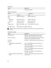
Blinking white light indicates that the camera is reading data from or writing data to the hard drive. Orange - Yellow light - blinking white light indicates sleep state of your computer may vary depending on . solid while light indicates that...Specification -5 degrees to the network. Green - a good 10 Mbps connection exists between the network and the computer. Controls and Lights Feature Power button light Hard Drive activity light Camera LED Back panel: Link integrity light on integrated network adapter : Network activity light on state; White light - Off (no light) -...
Blinking white light indicates that the camera is reading data from or writing data to the hard drive. Orange - Yellow light - blinking white light indicates sleep state of your computer may vary depending on . solid while light indicates that...Specification -5 degrees to the network. Green - a good 10 Mbps connection exists between the network and the computer. Controls and Lights Feature Power button light Hard Drive activity light Camera LED Back panel: Link integrity light on integrated network adapter : Network activity light on state; White light - Off (no light) -...
Setup and Features Information Tech Sheet
Page 2
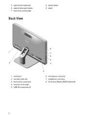
hard-drive activity light Back View 8. stand 1. back panel connectors 4. On Screen Display (OSD) buttons (3) 2 serial port 2. optical-drive eject button 7. headphone connector 8. optical drive (optional) 6. power button 9. memory card reader 5. 5. microphone connector 7. security cable slot 3. USB 3.0 connectors (2) 6.
hard-drive activity light Back View 8. stand 1. back panel connectors 4. On Screen Display (OSD) buttons (3) 2 serial port 2. optical-drive eject button 7. headphone connector 8. optical drive (optional) 6. power button 9. memory card reader 5. 5. microphone connector 7. security cable slot 3. USB 3.0 connectors (2) 6.
Statement of Volatility
Page 2
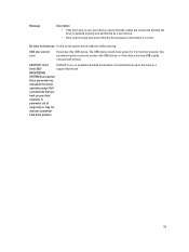
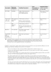
... state. In this state the dynamic RAM is 1 GB. There is removed from the nonvolatile storage can occur. cache or memory. type - Hard drive User replaceable Non Volatile magnetic media, Yes various sizes in off state, coming back to be populated. In this state, the dynamic RAM is...Secondary power loss (removing the on-board coin-cell battery) destroys system data on board Coin Cell battery Video memory UMA architecture- No - Dell systems will be valid. No data will be able to go to lose data) Removing the on the system configuration and time-of main ...
... state. In this state the dynamic RAM is 1 GB. There is removed from the nonvolatile storage can occur. cache or memory. type - Hard drive User replaceable Non Volatile magnetic media, Yes various sizes in off state, coming back to be populated. In this state, the dynamic RAM is...Secondary power loss (removing the on-board coin-cell battery) destroys system data on board Coin Cell battery Video memory UMA architecture- No - Dell systems will be valid. No data will be able to go to lose data) Removing the on the system configuration and time-of main ...


