User Manual
Page 1
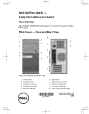
Front And Back View Figure 1. Front And Back View Of Mini-Tower 1. headphone connector 4. power button 2. USB 2.0 connectors (2) 9. hard-drive activity light 10. microphone connector 5. optical drive 7. power-supply diagnostic light Regulatory Model: D04S, D07D, D12M Regulatory Type: D04S001, D07D001, D12M001 2012 - 05 optical-drive eject button 8. Mini-Tower - diagnostic lights (4) 6. optical drive bay 3. Dell OptiPlex 390/3010 Setup And Features Information About Warnings WARNING: A WARNING indicates a potential for property damage, personal injury, or death.
Front And Back View Figure 1. Front And Back View Of Mini-Tower 1. headphone connector 4. power button 2. USB 2.0 connectors (2) 9. hard-drive activity light 10. microphone connector 5. optical drive 7. power-supply diagnostic light Regulatory Model: D04S, D07D, D12M Regulatory Type: D04S001, D07D001, D12M001 2012 - 05 optical-drive eject button 8. Mini-Tower - diagnostic lights (4) 6. optical drive bay 3. Dell OptiPlex 390/3010 Setup And Features Information About Warnings WARNING: A WARNING indicates a potential for property damage, personal injury, or death.
User Manual
Page 2
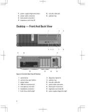
... connector 7. security cable slot 11. optical drive 2. expansion card slots (4) 14. padlock ring Desktop - USB 2.0 connectors (2) 5. microphone connector 6. padlock ring 10. power-supply diagnostic light 2 power cable connector 13. diagnostic lights (4) 9. power-supply diagnostic button 12. security cable slot 16. Front And Back View Figure 2. hard-drive activity light 8. 11. back panel connectors 14. expansion...
... connector 7. security cable slot 11. optical drive 2. expansion card slots (4) 14. padlock ring Desktop - USB 2.0 connectors (2) 5. microphone connector 6. padlock ring 10. power-supply diagnostic light 2 power cable connector 13. diagnostic lights (4) 9. power-supply diagnostic button 12. security cable slot 16. Front And Back View Figure 2. hard-drive activity light 8. 11. back panel connectors 14. expansion...
User Manual
Page 3
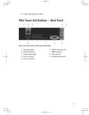
network connector 3. line-out connector 6. USB 2.0 connectors (6) 7. microphone connector 3 Back Panel Figure 3. Back Panel View of Mini-Tower And Desktop 1. link integrity light 2. network activity light 4. line-in connector 5. HDMI connector 8. 15. power-supply diagnostic button Mini-Tower And Desktop - VGA connector 9.
network connector 3. line-out connector 6. USB 2.0 connectors (6) 7. microphone connector 3 Back Panel Figure 3. Back Panel View of Mini-Tower And Desktop 1. link integrity light 2. network activity light 4. line-in connector 5. HDMI connector 8. 15. power-supply diagnostic button Mini-Tower And Desktop - VGA connector 9.

User Manual
Page 4
padlock ring 10. back panel connectors 15. hard-drive activity light 9. optical drive 2. USB 2.0 connectors (2) 5. optical-drive eject button 3. power-supply diagnostic button 13. security cable slot 11. expansion card slots (2) 4 Small Form Factor - Front And Back View Of Small Form Factor 1. microphone connector 6. Front And Back View Figure 4. power button 4. headphone connector 7. diagnostic lights (4) 8. power cable connector 12. power-supply diagnostic light 14.
padlock ring 10. back panel connectors 15. hard-drive activity light 9. optical drive 2. USB 2.0 connectors (2) 5. optical-drive eject button 3. power-supply diagnostic button 13. security cable slot 11. expansion card slots (2) 4 Small Form Factor - Front And Back View Of Small Form Factor 1. microphone connector 6. Front And Back View Figure 4. power button 4. headphone connector 7. diagnostic lights (4) 8. power cable connector 12. power-supply diagnostic light 14.

User Manual
Page 7
...) 175.00 mm Desktop 360.00 mm (14.17 inches) 102.00 mm Small Form Factor 290.00 mm (11.42 inches) 92.60 mm 7 Power Coin-cell battery Voltage Desktop/Mini-Tower/ Small Form Factor Wattage Desktop Mini-Tower Small Form Factor Maximum heat dissipation Desktop Mini-Tower Small Form... W 240 W 853 BTU/hr 904 BTU/hr 819 BTU/hr NOTE: Heat dissipation is calculated by law to ship with your computer, go to support.dell.com. Power Button Specifications NOTE: The following specifications are only those required by using the power supply wattage rating. Figure 11.
...) 175.00 mm Desktop 360.00 mm (14.17 inches) 102.00 mm Small Form Factor 290.00 mm (11.42 inches) 92.60 mm 7 Power Coin-cell battery Voltage Desktop/Mini-Tower/ Small Form Factor Wattage Desktop Mini-Tower Small Form Factor Maximum heat dissipation Desktop Mini-Tower Small Form... W 240 W 853 BTU/hr 904 BTU/hr 819 BTU/hr NOTE: Heat dissipation is calculated by law to ship with your computer, go to support.dell.com. Power Button Specifications NOTE: The following specifications are only those required by using the power supply wattage rating. Figure 11.
Guidebook
Page 3
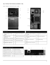
DELL™ OPTIPLEX™ 3010 TECHNICAL GUIDEBOOK -FINAL MINI TOWER COMPUTER (MT) VIEW 1 6 10 7 11 15 2 12 16 8 3 4 9 5 13 14 FRONT VIEW BACK VIEW 1 Power Button, Power Light 6 Optical Drive (optional) 2 Optical Drive Bay (optional) 7 Optical Drive Eject Button 3 Microphone Connector 8 USB 2.0 Connectors (2) 4 Headphone Connector 9 Drive Activity Light 10 Power Supply Diagnostic 14 Expansion Card Slots(4) Light 11...
DELL™ OPTIPLEX™ 3010 TECHNICAL GUIDEBOOK -FINAL MINI TOWER COMPUTER (MT) VIEW 1 6 10 7 11 15 2 12 16 8 3 4 9 5 13 14 FRONT VIEW BACK VIEW 1 Power Button, Power Light 6 Optical Drive (optional) 2 Optical Drive Bay (optional) 7 Optical Drive Eject Button 3 Microphone Connector 8 USB 2.0 Connectors (2) 4 Headphone Connector 9 Drive Activity Light 10 Power Supply Diagnostic 14 Expansion Card Slots(4) Light 11...
Guidebook
Page 5
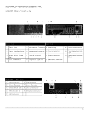
DELL™ OPTIPLEX™ 3010 TECHNICAL GUIDEBOOK -FINAL DESKTOP COMPUTER (DT) VIEW 1 2 3 9 10 11 4 56 7 8 12 13 14 15 FRONT VIEW 1 Optical Drive BACK VIEW 5 Microphone Connector 9 Padlock Ring 13 Expansion Card Slots(4) 2 Optical Drive Eject Button 6 Headphone Connector 10 Security Cable Slot 3 Power Button, Power Light 4 USB Connectors (2) 7 Drive Activity Light 8 Diagnostic Lights (4) 11 Power Connectors...
DELL™ OPTIPLEX™ 3010 TECHNICAL GUIDEBOOK -FINAL DESKTOP COMPUTER (DT) VIEW 1 2 3 9 10 11 4 56 7 8 12 13 14 15 FRONT VIEW 1 Optical Drive BACK VIEW 5 Microphone Connector 9 Padlock Ring 13 Expansion Card Slots(4) 2 Optical Drive Eject Button 6 Headphone Connector 10 Security Cable Slot 3 Power Button, Power Light 4 USB Connectors (2) 7 Drive Activity Light 8 Diagnostic Lights (4) 11 Power Connectors...
Guidebook
Page 7
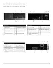
DELL™ OPTIPLEX™ 3010 TECHNICAL GUIDEBOOK -FINAL SMALL FORM FACTOR COMPUTER (SFF) VIEW 1 2 3 9 10 11 12 13 4 56 7 8 14 15 FRONT VIEW 1 Optical Drive 5 Microphone Connector 2 Optical Drive Eject Button 6 Headphone Connector 3 Power Button, Power Light 4 USB 2.0 Connectors (2) 7 Diagnostic Lights (4) 8 Drive Activity Light BACK VIEW 9 Padlock Ring 10 Security Cable Slot 11 Power Connectors 13 Power Supply... Diagnostic Light 14 Back Panel Connectors 15 Expansion Card Slots(2) 12 Power Supply Diagnostic Button BACK ...
DELL™ OPTIPLEX™ 3010 TECHNICAL GUIDEBOOK -FINAL SMALL FORM FACTOR COMPUTER (SFF) VIEW 1 2 3 9 10 11 12 13 4 56 7 8 14 15 FRONT VIEW 1 Optical Drive 5 Microphone Connector 2 Optical Drive Eject Button 6 Headphone Connector 3 Power Button, Power Light 4 USB 2.0 Connectors (2) 7 Diagnostic Lights (4) 8 Drive Activity Light BACK VIEW 9 Padlock Ring 10 Security Cable Slot 11 Power Connectors 13 Power Supply... Diagnostic Light 14 Back Panel Connectors 15 Expansion Card Slots(2) 12 Power Supply Diagnostic Button BACK ...
Guidebook
Page 15
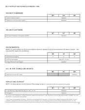
... please write Dell USA L.P., Attn: Warranties, One Dell Way, Round Rock, TX 78682. For more information, visit www.dell.com/warranty. 2 Service may be dispatched if necessary following phone-based troubleshooting. DELL™ OPTIPLEX™ 3010 TECHNICAL GUIDEBOOK ...MT DT SFF Optional ENVIRONMENTAL NOTE: For more details on Dell Service Plans please to go to Environmental Attributes section. See y o u r s p e c i fi c r e g i o n f o r a v a i l a b i l i t y . Sustainable packaging MultiPack packaging Energy Efficient Power Supply MT DT SFF X X X Optional, US only Optional...
... please write Dell USA L.P., Attn: Warranties, One Dell Way, Round Rock, TX 78682. For more information, visit www.dell.com/warranty. 2 Service may be dispatched if necessary following phone-based troubleshooting. DELL™ OPTIPLEX™ 3010 TECHNICAL GUIDEBOOK ...MT DT SFF Optional ENVIRONMENTAL NOTE: For more details on Dell Service Plans please to go to Environmental Attributes section. See y o u r s p e c i fi c r e g i o n f o r a v a i l a b i l i t y . Sustainable packaging MultiPack packaging Energy Efficient Power Supply MT DT SFF X X X Optional, US only Optional...
Guidebook
Page 18
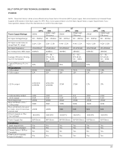
... +5.0v auxiliary output -12.0v output Max total power Max combined +3.3v / +5.0v power Max combined 12.0v power (note: only if more efficient Active Power Factor Correction (APFC) power supply. If you have questions, please contact the manufacture to confirm the output type. DELL™ OPTIPLEX™ 3010 TECHNICAL GUIDEBOOK -FINAL POWER NOTE: These form factors utilize a more than...
... +5.0v auxiliary output -12.0v output Max total power Max combined +3.3v / +5.0v power Max combined 12.0v power (note: only if more efficient Active Power Factor Correction (APFC) power supply. If you have questions, please contact the manufacture to confirm the output type. DELL™ OPTIPLEX™ 3010 TECHNICAL GUIDEBOOK -FINAL POWER NOTE: These form factors utilize a more than...
Guidebook
Page 19
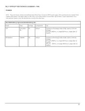
DELL™ OPTIPLEX™ 3010 TECHNICAL GUIDEBOOK -FINAL POWER NOTE: These form factors utilize a more efficient Active Power Factor Correction (APFC) power supply. If you have questions, please contact the manufacture to confirm the output type. 3.0v CMOS battery (Type and estimated battery life.... or Longer.910Hrs.or Longer after 12 months. 19 or Longer.820Hrs.or Longer after 12 months. 0℃±2℃. 850Hrs. Dell recommends only Universal Power Supplies (UPS) based on Sine Wave output for APFC PSUs, not an approximation of a Sine Wave, Square Wave, or quasi-Square Wave...
DELL™ OPTIPLEX™ 3010 TECHNICAL GUIDEBOOK -FINAL POWER NOTE: These form factors utilize a more efficient Active Power Factor Correction (APFC) power supply. If you have questions, please contact the manufacture to confirm the output type. 3.0v CMOS battery (Type and estimated battery life.... or Longer.910Hrs.or Longer after 12 months. 19 or Longer.820Hrs.or Longer after 12 months. 0℃±2℃. 850Hrs. Dell recommends only Universal Power Supplies (UPS) based on Sine Wave output for APFC PSUs, not an approximation of a Sine Wave, Square Wave, or quasi-Square Wave...

Owners Manual
Page 3
......24 Removing The System Fan...24 Installing The System Fan...26 Removing The Input/Output Panel...26 Installing The Input/Output Panel...27 Removing The Power Supply...27 Installing The Power Supply...29 Removing the System Board...30 Installing the System Board...31
......24 Removing The System Fan...24 Installing The System Fan...26 Removing The Input/Output Panel...26 Installing The Input/Output Panel...27 Removing The Power Supply...27 Installing The Power Supply...29 Removing the System Board...30 Installing the System Board...31

Owners Manual
Page 27
... Working Inside Your Computer. Related Links Installing The Input/Output Panel Installing The Input/Output Panel 1. Remove the PSU thermal sensor. 4. Disconnect the 4-pin power cable from the system board. 27 Remove the cover. 3. 7. Insert the Input/Output panel into the slot on the chassis front. 2. Follow the...Connect the Input/Output panel or the FlyWire cable to the chassis. 3. Install the cover. 7. Related Links Removing The Input/Output Panel Removing The Power Supply 1. Tighten the screw to secure the Input/Output panel to the chassis. 4. Remove the Input/Output panel.
... Working Inside Your Computer. Related Links Installing The Input/Output Panel Installing The Input/Output Panel 1. Remove the PSU thermal sensor. 4. Disconnect the 4-pin power cable from the system board. 27 Remove the cover. 3. 7. Insert the Input/Output panel into the slot on the chassis front. 2. Follow the...Connect the Input/Output panel or the FlyWire cable to the chassis. 3. Install the cover. 7. Related Links Removing The Input/Output Panel Removing The Power Supply 1. Tighten the screw to secure the Input/Output panel to the chassis. 4. Remove the Input/Output panel.

Owners Manual
Page 28
Unthread the 24-pin power cable from the system board. 7. Remove the screws that secure the power supply to the back of the computer. 28 Disconnect the 24-pin power cable from the chassis clip. 8. Unthread the 4-pin power cable from the chassis clips. 6. 5.
Unthread the 24-pin power cable from the system board. 7. Remove the screws that secure the power supply to the back of the computer. 28 Disconnect the 24-pin power cable from the chassis clip. 8. Unthread the 4-pin power cable from the chassis clips. 6. 5.

Owners Manual
Page 29
... and slide towards the front of the computer. 3. Connect the 4-pin power cable to secure the power supply from the back of the computer. 10. Related Links Installing The Power Supply Installing The Power Supply 1. Thread the 24-pin power cable into the chassis clips. 6. Lift the power supply out of the computer to the system board. 5. Install the cover...
... and slide towards the front of the computer. 3. Connect the 4-pin power cable to secure the power supply from the back of the computer. 10. Related Links Installing The Power Supply Installing The Power Supply 1. Thread the 24-pin power cable into the chassis clips. 6. Lift the power supply out of the computer to the system board. 5. Install the cover...

Owners Manual
Page 30
Remove the hard drive. 5. Remove the expansion cards. 6. Remove the screws that secure the system board to the system board. 8. Remove the cover. 3. Remove the heat sink. 7. Disconnect all the cables connected to the chassis. 10. Remove the front bezel. 4. Follow the procedures in Before Working Inside Your Computer. 2. Related Links Removing The Power Supply Removing the System Board 1. Lift and release the expansion-card latch to gain access to the screws securing the system board. 9. Slide the system board towards the front of the computer. 30
Remove the hard drive. 5. Remove the expansion cards. 6. Remove the screws that secure the system board to the system board. 8. Remove the cover. 3. Remove the heat sink. 7. Disconnect all the cables connected to the chassis. 10. Remove the front bezel. 4. Follow the procedures in Before Working Inside Your Computer. 2. Related Links Removing The Power Supply Removing the System Board 1. Lift and release the expansion-card latch to gain access to the screws securing the system board. 9. Slide the system board towards the front of the computer. 30

Owners Manual
Page 32
Follow the procedures in After Working Inside Your Computer. Secure the thermal sensor to the system board. 4. Related Links Installing The PSU Thermal Sensor Installing The PSU Thermal Sensor 1. Connect the thermal-sensor cable to the power supply. 2. Install the cover. 5. 4. Related Links Removing The PSU Thermal Sensor 32 Thread the thermal-sensor cable into the chassis clip. 3. Pry the thermal sensor away from the power supply and remove from the chassis clip. 5. Unthread the thermal-sensor cable from the chassis.
Follow the procedures in After Working Inside Your Computer. Secure the thermal sensor to the system board. 4. Related Links Installing The PSU Thermal Sensor Installing The PSU Thermal Sensor 1. Connect the thermal-sensor cable to the power supply. 2. Install the cover. 5. 4. Related Links Removing The PSU Thermal Sensor 32 Thread the thermal-sensor cable into the chassis clip. 3. Pry the thermal sensor away from the power supply and remove from the chassis clip. 5. Unthread the thermal-sensor cable from the chassis.
Owners Manual
Page 39
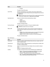
...in S4 and S5 This option is kept in standard 12-hour format (hour:minutes:seconds). This option is enabled by default. Allows you to power up from the LAN or wireless LAN. • LAN Only - This allows the operating system to enable or disable the keyboard error reporting ... Numlock LED Keyboard Errors POST Hotkeys Fast Boot Description • Last State This option is Disabled by default. Does not allow the system to AC power supply. • Disabled - Boot menu (enabled by default) This option can speed up the boot process by typing the values in the boot process. •...
...in S4 and S5 This option is kept in standard 12-hour format (hour:minutes:seconds). This option is enabled by default. Allows you to power up from the LAN or wireless LAN. • LAN Only - This allows the operating system to enable or disable the keyboard error reporting ... Numlock LED Keyboard Errors POST Hotkeys Fast Boot Description • Last State This option is Disabled by default. Does not allow the system to AC power supply. • Disabled - Boot menu (enabled by default) This option can speed up the boot process by typing the values in the boot process. •...

Owners Manual
Page 44
..., remove the modules, then re-install one memory module is with the power supply. Power Button Problem Description Troubleshooting Steps LED A possible system board, power supply, or peripheral failure has occurred. • Power off computer, leaving the computer plugged in. If it illuminates, there could...re-start the computer. • If available, install verified working electrical outlet and press the power button. Unplug the computer. Press and hold the power supply test button. If it to the switch does not illuminate, disconnect all modules without error. Plug...
..., remove the modules, then re-install one memory module is with the power supply. Power Button Problem Description Troubleshooting Steps LED A possible system board, power supply, or peripheral failure has occurred. • Power off computer, leaving the computer plugged in. If it illuminates, there could...re-start the computer. • If available, install verified working electrical outlet and press the power button. Unplug the computer. Press and hold the power supply test button. If it to the switch does not illuminate, disconnect all modules without error. Plug...

Owners Manual
Page 45
... Description Troubleshooting Steps LED A possible system board failure has occurred. Re-seat the 2x2 power connector from the PCI and PCI-E slots and re-start the computer. Power Button Problem Description Troubleshooting Steps LED Possible peripheral card or system board failure has occurred. Problem .... Remove all peripheral cards from the PCI and PCI-E slots and re-start the computer. Remove all peripheral cards from the power supply unit. The computer hardware is operating normally but the BIOS may be corrupt or missing. If the computer boots, add the peripheral...
... Description Troubleshooting Steps LED A possible system board failure has occurred. Re-seat the 2x2 power connector from the PCI and PCI-E slots and re-start the computer. Power Button Problem Description Troubleshooting Steps LED Possible peripheral card or system board failure has occurred. Problem .... Remove all peripheral cards from the PCI and PCI-E slots and re-start the computer. Remove all peripheral cards from the power supply unit. The computer hardware is operating normally but the BIOS may be corrupt or missing. If the computer boots, add the peripheral...


