Dell OptiPlex 3010 Support Question
Dell OptiPlex 3010 Support Question
Find answers below for this question about Dell OptiPlex 3010.Need a Dell OptiPlex 3010 manual? We have 5 online manuals for this item!
Question posted by Sunnyfun on February 22nd, 2014
Optiplex 3010 How To Remove The Power Supply
The person who posted this question about this Dell product did not include a detailed explanation. Please use the "Request More Information" button to the right if more details would help you to answer this question.
Current Answers
Related Dell OptiPlex 3010 Manual Pages
User Manual - Page 1
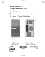
... Back View
Figure 1. optical drive bay 3. diagnostic lights (4)
6. power-supply diagnostic light
Regulatory Model: D04S, D07D, D12M Regulatory Type: D04S001, D07D001, D12M001 2012 - 05 Mini-Tower - optical drive 7. headphone connector 4. USB 2.0 connectors (2) 9. power button 2. Dell OptiPlex 390/3010
Setup And Features Information
About Warnings
WARNING: A WARNING indicates...
User Manual - Page 2
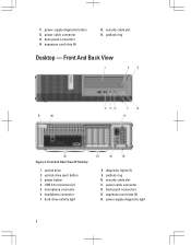
... 7. diagnostic lights (4) 9. back panel connectors 13. back panel connectors 14. power-supply diagnostic button 12. power button 4. microphone connector 6. power cable connector 13. expansion card slots (4)
15. optical drive 2. power-supply diagnostic light
2 11. security cable slot 16. padlock ring
Desktop - Front And Back View Of Desktop
1. padlock ring 10.
User Manual - Page 3
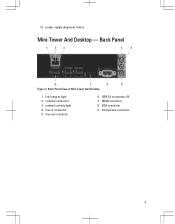
Back Panel View of Mini-Tower And Desktop
1. line-in connector 5. 15. link integrity light 2. microphone connector
3 power-supply diagnostic button
Mini-Tower And Desktop - line-out connector
6. Back Panel
Figure 3. HDMI connector 8. USB 2.0 connectors (6) 7. network activity light 4. VGA connector 9. network connector 3.
User Manual - Page 7

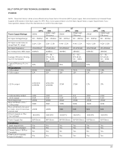
...are only those required by using the power supply wattage rating. Power Coin-cell battery Voltage
Desktop/Mini-Tower/ Small Form Factor Wattage Desktop Mini-Tower Small Form Factor Maximum heat dissipation Desktop Mini-Tower Small Form Factor
3 V ....
Physical Height
Width
Mini-Tower 360.00 mm (14.17 inches) 175.00 mm
Desktop 360.00 mm (14.17 inches) 102.00 mm
Small Form Factor 290.00 mm (11....
Statement of Volatility - Page 1

... lose their data even after the power has been removed from the component. Non-Volatile EEPROM
No
memory. 2Kbit (256 bytes)
One Device present on board
diags.)
256 bytes in
text)
One or two modules will be
populated. System memory
size will depend on the Dell OptiPlex 3010 motherboard:
Description
Reference Designator
Embedded U36...
Guidebook - Page 3
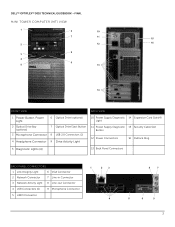
...; OPTIPLEX™ 3010 TECHNICAL GUIDEBOOK -FINAL
MINI TOWER COMPUTER (MT) VIEW
1
6
10
7
11
15
2
12
16
8 3
4
9
5
13
14
FRONT VIEW
BACK VIEW
1 Power Button, Power Light
6 Optical Drive (optional)
2 Optical Drive Bay (optional)
7 Optical Drive Eject Button
3 Microphone Connector 8 USB 2.0 Connectors (2)
4 Headphone Connector 9 Drive Activity Light
10 Power Supply Diagnostic...
Guidebook - Page 5
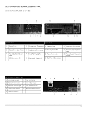
DELL™ OPTIPLEX™ 3010 TECHNICAL GUIDEBOOK -FINAL DESKTOP COMPUTER (DT) VIEW
1
2
3
9 10
11
4 56 7 8
12
13
14 15
FRONT VIEW 1 Optical Drive
BACK VIEW 5 Microphone Connector 9 Padlock Ring
13 Expansion Card Slots(4)
2 Optical Drive Eject Button 6 Headphone Connector 10 Security Cable Slot
3 Power Button, Power Light
4 USB Connectors (2)
7 Drive Activity Light 8 Diagnostic ...
Guidebook - Page 7
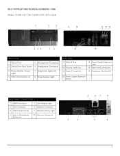
...; OPTIPLEX™ 3010 TECHNICAL GUIDEBOOK -FINAL SMALL FORM FACTOR COMPUTER (SFF) VIEW
1
2
3
9
10
11 12 13
4 56
7 8
14
15
FRONT VIEW
1 Optical Drive
5 Microphone Connector
2 Optical Drive Eject Button 6 Headphone Connector
3 Power Button, Power Light
4 USB 2.0 Connectors (2)
7 Diagnostic Lights (4) 8 Drive Activity Light
BACK VIEW 9 Padlock Ring
10 Security Cable Slot 11 Power...
Guidebook - Page 15
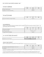
... Power Supply
MT
DT
SFF
X
X
X
Optional, US only
Optional
ALL-IN-ONE STANDS AND MOUNTS Small Form Factor AIO Stand
MT
DT
SFF
Optional
SERVICE AND SUPPORT
NOTE: For more information, visit www.dell.com/warranty.
2 Service may be dispatched if necessary following phone-based troubleshooting. Subject to Dell. DELL™ OPTIPLEX™ 3010...
Guidebook - Page 18
...0A 0.5A 235W 60W
N/A
819 BTU
60*25mm
Yes Yes Yes Yes
18 Power Supply Wattage AC input Voltage Range
265W
MT
APFC
EPA
265W High
Efficiency
90 - ...output Max total power Max combined +3.3v / +5.0v power Max combined 12.0v power (note: only if more efficient Active Power Factor Correction (APFC) power supply. DELL™ OPTIPLEX™ 3010 TECHNICAL GUIDEBOOK -FINAL POWER
NOTE: These ...
Guidebook - Page 19
... after 12 months. 0℃±2℃. 850Hrs. or Longer.910Hrs.or Longer after 12 months. DELL™ OPTIPLEX™ 3010 TECHNICAL GUIDEBOOK -FINAL POWER
NOTE: These form factors utilize a more efficient Active Power Factor Correction (APFC) power supply. If you have questions, please contact the manufacture to confirm the output type.
3.0v CMOS battery (Type and...
Guidebook - Page 33
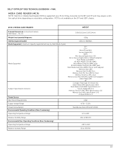
...02
Memory Stick (MS) Specification 1.43 xD Specification 1.2
Power Source
Max Power Requirements
2.5W
Supply Voltage Range
4.75V ~ 5.25V
Power Consumption: Environmental Operating Conditions (Non-Condensing):
Standby less than ... is supported via a F5 to 95% RH
33 DELL™ OPTIPLEX™ 3010 TECHNICAL GUIDEBOOK -FINAL
MEDIA CARD READER (MCR) NOTE: Dell 19 in 1 Media ...
Owners Manual - Page 28

Unthread the 24-pin power cable from the system board. 7. Disconnect the 24-pin power cable from the chassis clip. 8. Unthread the 4-pin power cable from the chassis clips. 6. Remove the screws that secure the power supply to the back of the computer. 28 5.
Owners Manual - Page 30

... expansion-card latch to gain access to the chassis.
10. Remove the screws that secure the system board to the screws securing the system board.
9. Remove the cover. 3. Disconnect all the cables connected to the system board.
8. Remove the expansion cards. 6. Related Links Removing The Power Supply
Removing the System Board
1. Follow the procedures in Before Working...
Owners Manual - Page 32

Connect the thermal-sensor cable to the power supply. 2. 4. Pry the thermal sensor away from the power supply and remove from the chassis clip.
5. Related Links
Removing The PSU Thermal Sensor 32 Secure the thermal sensor to the system board. 4. Thread the thermal-sensor cable into the chassis clip. 3. Related Links Installing ...
Owners Manual - Page 44

... normally, continue to install additional memory modules (one memory module is with a peripheral.
• If the LED still does not illuminate, remove the PSU connections from the system board, then press and hold the power supply test button. If only one at the rear of the same type into a working memory of the...
Owners Manual - Page 45

...computer boots, add the peripheral cards back one by one until you find the bad one . Power Button
45
Remove all peripheral cards from the PCI and PCI-E slots and re-start the computer.
The computer ...
BIOS may be corrupt or missing. Re-seat the 2x2 power connector from the PCI and PCI-E slots and re-start the computer. Remove all peripheral cards from the power supply unit.
Owners Manual - Page 60
...Fan
Mini-Tower, Desktop Small Form Factor Password clear jumper RTC reset jumper Internal speaker Intruder connector Power connector Controls and Lights Front of the computer: Power button light
Drive ... of the computer. Blinking amber light indicates a problem with the system board or power supply. blinking blue light indicates sleep state of the computer) and the electrical outlet.
...
Owners Manual - Page 61
...Lights
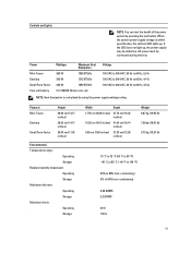
NOTE: You can test the health of the power system by using the power supply wattage rating.
Power
Mini-Tower Desktop Small Form Factor Coin-cell battery
Wattage
Maximum Heat ...-test LED lights up , the power supply may be connected during this test. If the LED does not light up . AC power must be defective. Physical Mini-Tower
Desktop
Small Form Factor
Height
36.00 cm...
User Manual - Page 3

... Battery...20 Installing The Coin-Cell Battery...21 Removing the Power-Switch Cable...21 Installing the Power-Switch Cable...22 Removing the System Fan...22 Installing The System Fan...24 Removing The Input/Output (I/O) Panel...24 Installing The Input/Output (I/O) Panel...25 Removing the Power Supply...26 Installing The Power Supply...27 Removing the System Board...28 Installing The System Board...
Similar Questions


How To Remove Power Supply From Dell Inspiron 660s
I can't find a way to take out the old power supply in my Inspiron 660s. It's loose but there I no r...
I can't find a way to take out the old power supply in my Inspiron 660s. It's loose but there I no r...
(Posted by sfishesfish 10 years ago)

How Many Watts Does A Optiplex 3010 Desktop Standard Power Supply
(Posted by doswbgste 10 years ago)