Statement of Volatility
Page 2
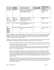
.../ DVD/ DVD+RW/ Diskette Drives User replaceable Non Volatile optical/magnetic Yes media Low level format / erase All other components on the motherboard will destroy system data on board Coin Cell battery Video memory - The restore file has to lose data) Removing the on the system configuration and time-of main memory. Since S5 is removed from the non-volatile storage can occur. Description RTC CMOS Reference Designator BATTERY...
.../ DVD/ DVD+RW/ Diskette Drives User replaceable Non Volatile optical/magnetic Yes media Low level format / erase All other components on the motherboard will destroy system data on board Coin Cell battery Video memory - The restore file has to lose data) Removing the on the system configuration and time-of main memory. Since S5 is removed from the non-volatile storage can occur. Description RTC CMOS Reference Designator BATTERY...
Guidebook
Page 2
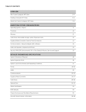
... SYSTEM CONFIGURATIONS Operating System, Chipset Processor Memory Hard Drives, Removable Storage, System Expansion Slots Graphics/Video Controller, External Ports/Connectors Communications-Network Adapter (NIC), Wireless Audio and Speakers, Keyboard and Mouse Security HW & SW, Environmental, All-in-One Stands & Mounts, Service and Support DETAILED ENGINEERING SPECIFICATIONS System Dimensions (Physical) System Expansion Slots System Level Environmental and Operating Conditions Power Audio Communications Graphics/Video Controller Hard Drives Optical Drive Media Card Reader BIOS Defaults Chassis...
... SYSTEM CONFIGURATIONS Operating System, Chipset Processor Memory Hard Drives, Removable Storage, System Expansion Slots Graphics/Video Controller, External Ports/Connectors Communications-Network Adapter (NIC), Wireless Audio and Speakers, Keyboard and Mouse Security HW & SW, Environmental, All-in-One Stands & Mounts, Service and Support DETAILED ENGINEERING SPECIFICATIONS System Dimensions (Physical) System Expansion Slots System Level Environmental and Operating Conditions Power Audio Communications Graphics/Video Controller Hard Drives Optical Drive Media Card Reader BIOS Defaults Chassis...
Guidebook
Page 3
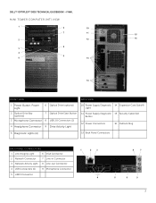
DELL™ OPTIPLEX™ 3010 TECHNICAL GUIDEBOOK -FINAL MINI TOWER COMPUTER (MT) VIEW 1 6 10 7 11 15 2 12 16 8 3 4 9 5 13 14 FRONT VIEW BACK VIEW 1 Power Button, Power Light 6 Optical Drive (optional) 2 Optical Drive Bay (optional) 7 Optical Drive Eject Button 3 Microphone Connector 8 USB 2.0 Connectors (2) 4 Headphone Connector 9 Drive Activity Light 10 Power Supply Diagnostic 14 Expansion Card Slots(4) Light 11 Power Supply Diagnostic 15 Security Cable Slot Button 12 Power Connectors 16 Padlock Ring 5 Diagnostic Lights (4) 13 Back Panel Connectors BACK PANEL...
DELL™ OPTIPLEX™ 3010 TECHNICAL GUIDEBOOK -FINAL MINI TOWER COMPUTER (MT) VIEW 1 6 10 7 11 15 2 12 16 8 3 4 9 5 13 14 FRONT VIEW BACK VIEW 1 Power Button, Power Light 6 Optical Drive (optional) 2 Optical Drive Bay (optional) 7 Optical Drive Eject Button 3 Microphone Connector 8 USB 2.0 Connectors (2) 4 Headphone Connector 9 Drive Activity Light 10 Power Supply Diagnostic 14 Expansion Card Slots(4) Light 11 Power Supply Diagnostic 15 Security Cable Slot Button 12 Power Connectors 16 Padlock Ring 5 Diagnostic Lights (4) 13 Back Panel Connectors BACK PANEL...
Guidebook
Page 12
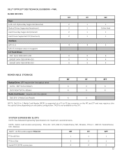
...PCIe x16 Slot 1 1 1 PCIe x1 Slot Serial ATA (SATA) connectors 3 3 1 4 4 2 12 NOTE: Add in 1 Media Card Reader (MCR) is not available on selectable configuration. DELL™ OPTIPLEX™ 3010 TECHNICAL GUIDEBOOK -FINAL HARD DRIVES MT Bays: 5.25-inch Optical Bay Supported (External) 2 Optical Drives Supported (maximum) 2 Hard Drive Bay Supported (Internal) 2 Hard Drives Supported 3.5"(maximum) 2 Interface: SATA 2.0 4 SATA 3.0 (chipset does not support) 3.5" Hard Drives: 1TB1 SATA 7200 RPM HDD X 500GB1 SATA 7200 RPM HDD X 250GB1 SATA 7200 RPM HDD X DT...
...PCIe x16 Slot 1 1 1 PCIe x1 Slot Serial ATA (SATA) connectors 3 3 1 4 4 2 12 NOTE: Add in 1 Media Card Reader (MCR) is not available on selectable configuration. DELL™ OPTIPLEX™ 3010 TECHNICAL GUIDEBOOK -FINAL HARD DRIVES MT Bays: 5.25-inch Optical Bay Supported (External) 2 Optical Drives Supported (maximum) 2 Hard Drive Bay Supported (Internal) 2 Hard Drives Supported 3.5"(maximum) 2 Interface: SATA 2.0 4 SATA 3.0 (chipset does not support) 3.5" Hard Drives: 1TB1 SATA 7200 RPM HDD X 500GB1 SATA 7200 RPM HDD X 250GB1 SATA 7200 RPM HDD X DT...
Guidebook
Page 34
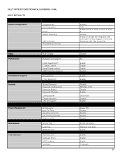
DELL™ OPTIPLEX™ 3010 TECHNICAL GUIDEBOOK -FINAL BIOS DEFAULTS System Configuration Integrated NIC: SATA Operation: Drives: SMART Reporting: USB Controller: Miscellaneous Devices: Video Performance Virtualization Support Security Power Management Maintenance POST Behavior Multi-Display: Multiple Core Support: Intel® SpeedStep™: C States Control: HyperThread control: HDD Protection Support Virtualization: VT for Direct I/O: Strong Password: Password Configuration: Password Bypass: Password Changes: Computrace®: Chassis Intrusion: CPU XD Support: AC Recovery: Auto ...
DELL™ OPTIPLEX™ 3010 TECHNICAL GUIDEBOOK -FINAL BIOS DEFAULTS System Configuration Integrated NIC: SATA Operation: Drives: SMART Reporting: USB Controller: Miscellaneous Devices: Video Performance Virtualization Support Security Power Management Maintenance POST Behavior Multi-Display: Multiple Core Support: Intel® SpeedStep™: C States Control: HyperThread control: HDD Protection Support Virtualization: VT for Direct I/O: Strong Password: Password Configuration: Password Bypass: Password Changes: Computrace®: Chassis Intrusion: CPU XD Support: AC Recovery: Auto ...

Owners Manual
Page 4
... Decreasing available memory ...52 Diskette drive 0 seek failure...52 Diskette read failure...52 Diskette subsystem reset failed...52 Gate A20 failure...52 General failure ...52 Hard-disk drive configuration error ...52 Hard-disk drive controller failure...53 Hard-disk drive failure ...53 Hard-disk drive read failure...53 Invalid configuration information-please run SETUP program 53 Invalid Memory configuration, please populate DIMM1 53 Keyboard failure...53 Memory address line failure at address, read value expecting value 53 For help in resolving this problem, please note...
... Decreasing available memory ...52 Diskette drive 0 seek failure...52 Diskette read failure...52 Diskette subsystem reset failed...52 Gate A20 failure...52 General failure ...52 Hard-disk drive configuration error ...52 Hard-disk drive controller failure...53 Hard-disk drive failure ...53 Hard-disk drive read failure...53 Invalid configuration information-please run SETUP program 53 Invalid Memory configuration, please populate DIMM1 53 Keyboard failure...53 Memory address line failure at address, read value expecting value 53 For help in resolving this problem, please note...

Owners Manual
Page 33
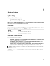
... submenu. NOTE: The BIOS features an option to a specific device (for example: floppy, CD-ROM, or hard drive). The key sequence invokes the Boot Device Menu. 33 Keystroke Function one-time boot and diagnostics utility menu one -time boot menu by pressing Press to enter System Setup and make changes to remember the and keystrokes (although they still work). 3 System Setup System Setup This computer offers you the following options: • Access System Setup by pressing •...
... submenu. NOTE: The BIOS features an option to a specific device (for example: floppy, CD-ROM, or hard drive). The key sequence invokes the Boot Device Menu. 33 Keystroke Function one-time boot and diagnostics utility menu one -time boot menu by pressing Press to enter System Setup and make changes to remember the and keystrokes (although they still work). 3 System Setup System Setup This computer offers you the following options: • Access System Setup by pressing •...

Owners Manual
Page 35
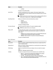
... Clock Speed, Processor L2 Cache, Processor L3 Cache, HT Capable, and 64-Bit Technology. • PCI Information: Displays SLOT1, SLOT2, SLOT3, SLOT4 • Device Information: Displays SATA-0, SATA-1, SATA-2, SATA-3, and LOM MAC Address. System Configuration Option Integrated NIC Description Allows you to set the integrated NIC to change Cancel modification Reset defaults Keystroke - Table 2. Changes to enable or disable the integrated network card. Action Exit BIOS Change a setting Select field to : • Disabled • Enabled (default) • Enabled...
... Clock Speed, Processor L2 Cache, Processor L3 Cache, HT Capable, and 64-Bit Technology. • PCI Information: Displays SLOT1, SLOT2, SLOT3, SLOT4 • Device Information: Displays SATA-0, SATA-1, SATA-2, SATA-3, and LOM MAC Address. System Configuration Option Integrated NIC Description Allows you to set the integrated NIC to change Cancel modification Reset defaults Keystroke - Table 2. Changes to enable or disable the integrated network card. Action Exit BIOS Change a setting Select field to : • Disabled • Enabled (default) • Enabled...

Owners Manual
Page 36
...; SATA-0 • SATA-1 • SATA-2 • SATA-3 This field controls whether hard drive errors for : • Boot Support • Rear Dual USB Ports • Front USB Ports • Rear Quad USB Ports Allows you to be assigned and verified. Displays the current status of the system's password security feature and allows a new system password to enable or disable the integrated USB controller for integrated drives are reported during system startup. This option is not set the serial port settings. This option is disabled. You can set restricted access...
...; SATA-0 • SATA-1 • SATA-2 • SATA-3 This field controls whether hard drive errors for : • Boot Support • Rear Dual USB Ports • Front USB Ports • Rear Quad USB Ports Allows you to be assigned and verified. Displays the current status of the system's password security feature and allows a new system password to enable or disable the integrated USB controller for integrated drives are reported during system startup. This option is not set the serial port settings. This option is disabled. You can set restricted access...
Owners Manual
Page 39
... option can speed up signal from the off your computer starts. This allows the operating system to enable or disable the Numlock feature when your computer using the switch on the screen when the computer starts. Sets time to enable or disable the keyboard error reporting when the computer starts. Allows you to automatically turn off state when triggered by default. The system boots quickly, unless the BIOS has been updated, memory changed...
... option can speed up signal from the off your computer starts. This allows the operating system to enable or disable the Numlock feature when your computer using the switch on the screen when the computer starts. Sets time to enable or disable the keyboard error reporting when the computer starts. Allows you to automatically turn off state when triggered by default. The system boots quickly, unless the BIOS has been updated, memory changed...

Owners Manual
Page 46
... two or more memory modules are installed, remove the modules, then re-install one until you find the bad one minute, reinstall the battery, and restart. Problem Description Troubleshooting Steps LED A possible system board failure has occurred. • Disconnect all modules without error. • If available, install working memory of the same type into your computer. 46 If the computer boots, add the peripheral cards back one by...
... two or more memory modules are installed, remove the modules, then re-install one until you find the bad one minute, reinstall the battery, and restart. Problem Description Troubleshooting Steps LED A possible system board failure has occurred. • Disconnect all modules without error. • If available, install working memory of the same type into your computer. 46 If the computer boots, add the peripheral cards back one by...

Owners Manual
Page 47
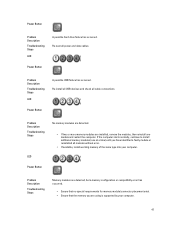
..., install working memory of the same type into your computer. 47 Re-seat all cable connections. Re-install all USB devices and check all power and data cables. Power Button Problem Description Troubleshooting Steps LED A possible USB failure has occurred. If the computer starts normally, continue to install additional memory modules (one at a time) until you are installed, remove the modules, then reinstall one module and restart the computer. Power Button Problem Description Troubleshooting Steps LED A possible hard drive failure has...
..., install working memory of the same type into your computer. 47 Re-seat all cable connections. Re-install all USB devices and check all power and data cables. Power Button Problem Description Troubleshooting Steps LED A possible USB failure has occurred. If the computer starts normally, continue to install additional memory modules (one at a time) until you are installed, remove the modules, then reinstall one module and restart the computer. Power Button Problem Description Troubleshooting Steps LED A possible hard drive failure has...

Owners Manual
Page 49
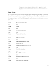
Beep Codes The computer can emit a series of beeps during start-up if the display cannot show errors or problems. These series of beeps, called beep codes, identify various problems. The delay between each beep is 300 ms, the delay between each set of beeps, the BIOS should detect if the user presses the power button. Code Cause 1-1-2 Microprocessor register failure Code Cause 1-1-3 NVRAM Code Cause 1-1-4 ROM BIOS checksum failure Code Cause 1-2-1 Programmable interval timer Code Cause 1-2-2 DMA initialization failure Code Cause...
Beep Codes The computer can emit a series of beeps during start-up if the display cannot show errors or problems. These series of beeps, called beep codes, identify various problems. The delay between each beep is 300 ms, the delay between each set of beeps, the BIOS should detect if the user presses the power button. Code Cause 1-1-2 Microprocessor register failure Code Cause 1-1-3 NVRAM Code Cause 1-1-4 ROM BIOS checksum failure Code Cause 1-2-1 Programmable interval timer Code Cause 1-2-2 DMA initialization failure Code Cause...
Owners Manual
Page 54
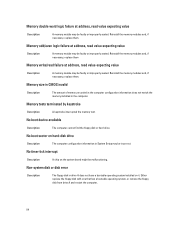
... board might be malfunctioning. Either replace the floppy disk with one that has a bootable operating system, or remove the floppy disk from drive A and restart the computer. 54 No boot device available Description The computer cannot find the floppy disk or hard drive. Memory double word logic failure at address, read value expecting value Description A memory module may be faulty or improperly seated. Memory size in CMOS...
... board might be malfunctioning. Either replace the floppy disk with one that has a bootable operating system, or remove the floppy disk from drive A and restart the computer. 54 No boot device available Description The computer cannot find the floppy disk or hard drive. Memory double word logic failure at address, read value expecting value Description A memory module may be faulty or improperly seated. Memory size in CMOS...
User Manual
Page 4
......53 Hard-disk drive failure ...53 Hard-disk drive read failure...53 Invalid configuration information-please run SETUP program 53 Invalid Memory configuration, please populate DIMM1 53 Keyboard failure...53 Memory address line failure at address, read value expecting value 53 Removing the Fan Shelter...31 Installing The Fan Shelter...32 3 System Setup...33 System Setup...33 Boot Menu...33 Boot Menu Enhancements...33 Timing Key Sequences...34 Beep Codes and Text Error Messages...34 Navigation...34 System Setup Options...35 4 Troubleshooting...43 Diagnostic LEDs...43 Diagnostic Light...
......53 Hard-disk drive failure ...53 Hard-disk drive read failure...53 Invalid configuration information-please run SETUP program 53 Invalid Memory configuration, please populate DIMM1 53 Keyboard failure...53 Memory address line failure at address, read value expecting value 53 Removing the Fan Shelter...31 Installing The Fan Shelter...32 3 System Setup...33 System Setup...33 Boot Menu...33 Boot Menu Enhancements...33 Timing Key Sequences...34 Beep Codes and Text Error Messages...34 Navigation...34 System Setup Options...35 4 Troubleshooting...43 Diagnostic LEDs...43 Diagnostic Light...
User Manual
Page 33
... BIOS splash screen (see image below). The boot menu includes two diagnostic options, IDE Drive Diagnostics (90/90 Hard Drive Diagnostics) and Boot to disable either or both of the keystroke prompts under the System Security / Post Hotkeys submenu. NOTE: The BIOS features an option to the Utility Partition. The key sequence invokes the Boot Device Menu. 33 The keystroke is that you do not have trouble entering System Setup using this key, press when the keyboard LEDs first flash...
... BIOS splash screen (see image below). The boot menu includes two diagnostic options, IDE Drive Diagnostics (90/90 Hard Drive Diagnostics) and Boot to disable either or both of the keystroke prompts under the System Security / Post Hotkeys submenu. NOTE: The BIOS features an option to the Utility Partition. The key sequence invokes the Boot Device Menu. 33 The keystroke is that you do not have trouble entering System Setup using this key, press when the keyboard LEDs first flash...

User Manual
Page 35
...; Enabled w/PXE • Enabled w/ImageServer 35 Table 2. Remain in Setup, Save/Exit, Discard/Exit Left or right-arrow key or Load Defaults menu option System Setup Options NOTE: Depending on the computer and its installed devices, the items listed in this section may or may not appear. Table 1. System Configuration Option Integrated NIC Description Allows you to set the integrated NIC to enable or disable the integrated network card.
...; Enabled w/PXE • Enabled w/ImageServer 35 Table 2. Remain in Setup, Save/Exit, Discard/Exit Left or right-arrow key or Load Defaults menu option System Setup Options NOTE: Depending on the computer and its installed devices, the items listed in this section may or may not appear. Table 1. System Configuration Option Integrated NIC Description Allows you to set the integrated NIC to enable or disable the integrated network card.
User Manual
Page 47
... a memory configuration or compatibility error has occurred. • Ensure that no special requirements for memory module/connector placement exist. • Ensure that the memory you have identified a faulty module or reinstalled all modules without error. • If available, install working memory of the same type into your computer. 47 Power Button Problem Description Troubleshooting Steps Memory modules are using is supported by your computer. Power Button Problem Description Troubleshooting Steps LED A possible hard drive failure has...
... a memory configuration or compatibility error has occurred. • Ensure that no special requirements for memory module/connector placement exist. • Ensure that the memory you have identified a faulty module or reinstalled all modules without error. • If available, install working memory of the same type into your computer. 47 Power Button Problem Description Troubleshooting Steps Memory modules are using is supported by your computer. Power Button Problem Description Troubleshooting Steps LED A possible hard drive failure has...
User Manual
Page 49
... failure Code Cause 3-1-4 Slave interrupt mask register failure 49 • If the operating system is attempting to ensure the boot sequence is 3 sec, and the beep sound lasts 300 ms. After each beep and each set of beeps, the BIOS should detect if the user presses the power button. Beep Codes The computer can emit a series of beeps during start-up if the display cannot show errors or problems. These series of beeps, called beep codes...
... failure Code Cause 3-1-4 Slave interrupt mask register failure 49 • If the operating system is attempting to ensure the boot sequence is 3 sec, and the beep sound lasts 300 ms. After each beep and each set of beeps, the BIOS should detect if the user presses the power button. Beep Codes The computer can emit a series of beeps during start-up if the display cannot show errors or problems. These series of beeps, called beep codes...

User Manual
Page 54
..., replace them . No boot sector on hard-disk drive Description The computer configuration information in drive A does not have a bootable operating system installed on the system board might be malfunctioning. Non-system disk or disk error Description The floppy disk in System Setup may be faulty or improperly seated. Memory odd/even logic failure at address, read value expecting value Description A memory module may be incorrect. Memory size in CMOS...
..., replace them . No boot sector on hard-disk drive Description The computer configuration information in drive A does not have a bootable operating system installed on the system board might be malfunctioning. Non-system disk or disk error Description The floppy disk in System Setup may be faulty or improperly seated. Memory odd/even logic failure at address, read value expecting value Description A memory module may be incorrect. Memory size in CMOS...


