Service Manual
Page 5
Dell™ Latitude™ L400 Service Manual This manual provides instructions for removing and replacing field-replaceable components, assemblies, and subassemblies in this manual, the locations or directions relative to ... of the computer. • A part can be replaced by performing the removal procedure in Figure 1 unless otherwise specified. Unless otherwise noted, each procedure in your Dell Latitude computer. back of computer left side right side front of computer Figure 1. Computer Orientation support.dell.com Dell Latitude L400 Service Manual 1
Dell™ Latitude™ L400 Service Manual This manual provides instructions for removing and replacing field-replaceable components, assemblies, and subassemblies in this manual, the locations or directions relative to ... of the computer. • A part can be replaced by performing the removal procedure in Figure 1 unless otherwise specified. Unless otherwise noted, each procedure in your Dell Latitude computer. back of computer left side right side front of computer Figure 1. Computer Orientation support.dell.com Dell Latitude L400 Service Manual 1
Service Manual
Page 6
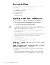
... to prevent scratching the computer cover. Remove the power cable. 6. If you service the computer. 8. NOTICE: Make sure that the computer is docked in the L400 Advanced Port Replicator (APR), undock the computer. 4. Disconnect the computer and any attached peripherals from the computer. 7. Remove any telephone or telecommunications lines from the... from the computer. 5. Recommended Tools Most of the procedures in this manual require the use of one or more of the battery bay (see Figure 2). 2 Dell Latitude L400 Service Manual
... to prevent scratching the computer cover. Remove the power cable. 6. If you service the computer. 8. NOTICE: Make sure that the computer is docked in the L400 Advanced Port Replicator (APR), undock the computer. 4. Disconnect the computer and any attached peripherals from the computer. 7. Remove any telephone or telecommunications lines from the... from the computer. 5. Recommended Tools Most of the procedures in this manual require the use of one or more of the battery bay (see Figure 2). 2 Dell Latitude L400 Service Manual
Service Manual
Page 7
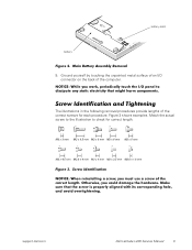
... unpainted metal surface of the computer. Screw Identification and Tightening The illustrations in the following removal procedures provide lengths of the correct length. Figure 3. support.dell.com Dell Latitude L400 Service Manual 3 battery latch battery Figure 2.
... unpainted metal surface of the computer. Screw Identification and Tightening The illustrations in the following removal procedures provide lengths of the correct length. Figure 3. support.dell.com Dell Latitude L400 Service Manual 3 battery latch battery Figure 2.
Service Manual
Page 8
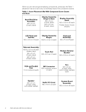
Screw Placement Mat With Component Screw Counts and Sizes Hard-Disk Drive Assembly: M3 x 3 mm (2 each ) 4 Dell Latitude L400 Service Manual Table 1. When you are removing and replacing components, photocopy the Table 1 placement mat as a tool to Base: M2 x 4 mm (2 each, black) M2 x 4.5 mm (2 ...
Screw Placement Mat With Component Screw Counts and Sizes Hard-Disk Drive Assembly: M3 x 3 mm (2 each ) 4 Dell Latitude L400 Service Manual Table 1. When you are removing and replacing components, photocopy the Table 1 placement mat as a tool to Base: M2 x 4 mm (2 each, black) M2 x 4.5 mm (2 ...
Service Manual
Page 9
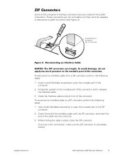
...) Figure 4. To ensure a firm connection, make sure the ZIF connector is completely closed. Grasp the interface cable and pull it releases the interface cable. 3. support.dell.com Dell Latitude L400 Service Manual 5 To avoid damage, do not apply too much pressure to a ZIF connector, perform the following steps: 1. movable part of the connector. To...
...) Figure 4. To ensure a firm connection, make sure the ZIF connector is completely closed. Grasp the interface cable and pull it releases the interface cable. 3. support.dell.com Dell Latitude L400 Service Manual 5 To avoid damage, do not apply too much pressure to a ZIF connector, perform the following steps: 1. movable part of the connector. To...
Service Manual
Page 10
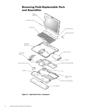
Removing Field-Replaceable Parts and Assemblies display assembly left hinge cover keyboard keyboard bezel right hinge cover palmrest assembly audio EMI shield audio I/O port cover speaker hard-disk drive modem system board assembly fan APR docking doors bottom case assembly main battery Figure 5. Exploded View-Computer 6 Dell Latitude L400 Service Manual
Removing Field-Replaceable Parts and Assemblies display assembly left hinge cover keyboard keyboard bezel right hinge cover palmrest assembly audio EMI shield audio I/O port cover speaker hard-disk drive modem system board assembly fan APR docking doors bottom case assembly main battery Figure 5. Exploded View-Computer 6 Dell Latitude L400 Service Manual
Service Manual
Page 11
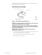
... main battery before you service the computer. Turn the computer over, and remove the two M3 x 3-mm screws from the bottom of the computer. support.dell.com Dell Latitude L400 Service Manual 7 The hard-disk drive is very sensitive to prevent scratching the computer cover. 1. NOTICE: The hard-disk drive is located on the...
... main battery before you service the computer. Turn the computer over, and remove the two M3 x 3-mm screws from the bottom of the computer. support.dell.com Dell Latitude L400 Service Manual 7 The hard-disk drive is very sensitive to prevent scratching the computer cover. 1. NOTICE: The hard-disk drive is located on the...
Service Manual
Page 12
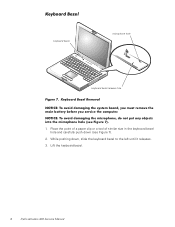
... bezel release hole Figure 7. NOTICE: To avoid damaging the microphone, do not put any objects into the microphone hole (see Figure 7). 2. Lift the keyboard bezel. 8 Dell Latitude L400 Service Manual
... bezel release hole Figure 7. NOTICE: To avoid damaging the microphone, do not put any objects into the microphone hole (see Figure 7). 2. Lift the keyboard bezel. 8 Dell Latitude L400 Service Manual
Service Manual
Page 13
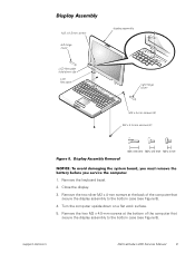
.... 2. Remove the two M2 x 4.5-mm screws at the back of the computer that secure the display assembly to the bottom case (see Figure 8). 4. support.dell.com Dell Latitude L400 Service Manual 9 Remove the two silver M2 x 4-mm screws at the bottom of the computer that secure the display assembly to the bottom case (see...
.... 2. Remove the two M2 x 4.5-mm screws at the back of the computer that secure the display assembly to the bottom case (see Figure 8). 4. support.dell.com Dell Latitude L400 Service Manual 9 Remove the two silver M2 x 4-mm screws at the bottom of the computer that secure the display assembly to the bottom case (see...
Service Manual
Page 14
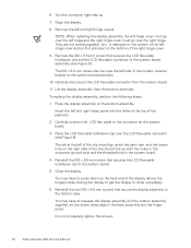
... the system board. 5. Place the LCD flex-cable hold -down clip over the right hinge. Close the display. Do not completely tighten the screws. 10 Dell Latitude L400 Service Manual
... the system board. 5. Place the LCD flex-cable hold -down clip over the right hinge. Close the display. Do not completely tighten the screws. 10 Dell Latitude L400 Service Manual
Service Manual
Page 15
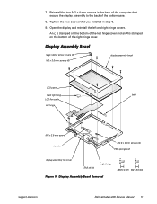
... hinge latch M2 x 3.5-mm screw inverter M2.6 x 4-mm screws (4) EMI sponges (2) display-assembly top cover EMI shield right hinge Figure 9. Display Assembly Bezel Removal support.dell.com Dell Latitude L400 Service Manual 11
... hinge latch M2 x 3.5-mm screw inverter M2.6 x 4-mm screws (4) EMI sponges (2) display-assembly top cover EMI shield right hinge Figure 9. Display Assembly Bezel Removal support.dell.com Dell Latitude L400 Service Manual 11
Service Manual
Page 16
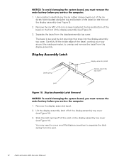
... cover. Carefully lift the inside edge of the bezel, working your way around the inside perimeter, to separate the latch spring from the post. 12 Dell Latitude L400 Service Manual Display Assembly Latch display assembly latch latch spring display assembly top cover post Figure 10. Remove the display assembly bezel. 2. Slide the latch...
... cover. Carefully lift the inside edge of the bezel, working your way around the inside perimeter, to separate the latch spring from the post. 12 Dell Latitude L400 Service Manual Display Assembly Latch display assembly latch latch spring display assembly top cover post Figure 10. Remove the display assembly bezel. 2. Slide the latch...
Service Manual
Page 17
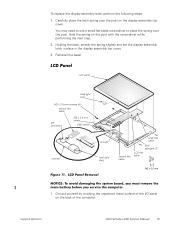
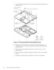
... M2 x 3.5-mm screw EMI shield inverter inverter back light plug wide flex cable narrow flex cable EMI sponges (2) LCD flex cable Figure 11. support.dell.com Dell Latitude L400 Service Manual 13 LCD Panel Removal NOTICE: To avoid damaging the system board, you must remove the main battery before you service the computer. 1. Reinstall...
... M2 x 3.5-mm screw EMI shield inverter inverter back light plug wide flex cable narrow flex cable EMI sponges (2) LCD flex cable Figure 11. support.dell.com Dell Latitude L400 Service Manual 13 LCD Panel Removal NOTICE: To avoid damaging the system board, you must remove the main battery before you service the computer. 1. Reinstall...
Service Manual
Page 18
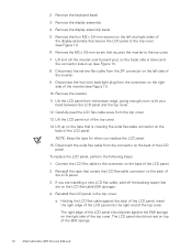
.... 5. Carefully peel the LCD flex cable away from the bottom edge, giving enough room to the connector on the back of the EMI sponge. 14 Dell Latitude L400 Service Manual Lift the LCD panel from the top cover. 13. Connect the LCD flex cable to fit your hand between the LCD panel and...
.... 5. Carefully peel the LCD flex cable away from the bottom edge, giving enough room to the connector on the back of the EMI sponge. 14 Dell Latitude L400 Service Manual Lift the LCD panel from the top cover. 13. Connect the LCD flex cable to fit your hand between the LCD panel and...
Service Manual
Page 19
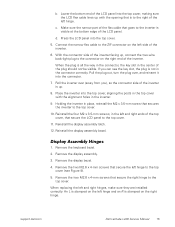
..., that secure the right hinge to the top cover. 10. Remove the two M2.6 x 4-mm screws that goes to the top cover. 11. support.dell.com Dell Latitude L400 Service Manual 15 Make sure the narrow part of the flex cable that secure the left side of the plug should not be visible. Pull...
..., that secure the right hinge to the top cover. 10. Remove the two M2.6 x 4-mm screws that goes to the top cover. 11. support.dell.com Dell Latitude L400 Service Manual 15 Make sure the narrow part of the flex cable that secure the left side of the plug should not be visible. Pull...
Service Manual
Page 20
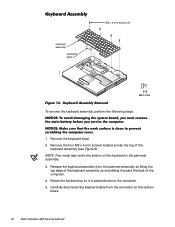
... system board, you must remove the main battery before you service the computer. Release the keyboard assembly from the connector on the system board. 16 Dell Latitude L400 Service Manual NOTE: Five metal tabs retain the bottom of the keyboard in the palmrest assembly. 3. NOTICE: Make sure that the work surface is perpendicular...
... system board, you must remove the main battery before you service the computer. Release the keyboard assembly from the connector on the system board. 16 Dell Latitude L400 Service Manual NOTE: Five metal tabs retain the bottom of the keyboard in the palmrest assembly. 3. NOTICE: Make sure that the work surface is perpendicular...
Service Manual
Page 21
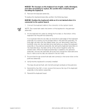
... cable to enter the slotted holes. Verify that the top screw-hole tabs rest correctly in the screw slots on the palmrest assembly. 4. support.dell.com Dell Latitude L400 Service Manual 17 NOTICE: Position the keyboard cable so it is not twisted when it is important that secure the top of the keyboard into...
... cable to enter the slotted holes. Verify that the top screw-hole tabs rest correctly in the screw slots on the palmrest assembly. 4. support.dell.com Dell Latitude L400 Service Manual 17 NOTICE: Position the keyboard cable so it is not twisted when it is important that secure the top of the keyboard into...
Service Manual
Page 22
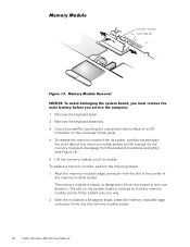
.... 3. Lift the memory module out of the memory module socket just far enough for the memory module to fit into the memory module socket. 18 Dell Latitude L400 Service Manual Ground yourself by touching the unpainted metal surface of the memory module socket. To replace a memory module, perform the following steps: 1. Align the...
.... 3. Lift the memory module out of the memory module socket just far enough for the memory module to fit into the memory module socket. 18 Dell Latitude L400 Service Manual Ground yourself by touching the unpainted metal surface of the memory module socket. To replace a memory module, perform the following steps: 1. Align the...
Service Manual
Page 23
... down until it clicks into the tabs, remove the memory module and reinstall it (see Figure 14). NOTICE: Make sure that the work surface. 5. support.dell.com Dell Latitude L400 Service Manual 19 3. Remove the keyboard bezel. 2. Remove the display assembly. 3.
... down until it clicks into the tabs, remove the memory module and reinstall it (see Figure 14). NOTICE: Make sure that the work surface. 5. support.dell.com Dell Latitude L400 Service Manual 19 3. Remove the keyboard bezel. 2. Remove the display assembly. 3.
Service Manual
Page 24
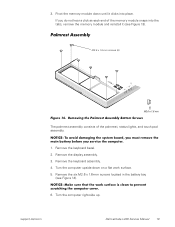
.... Disconnect the touch pad flex cable from the ZIF connector on the system board. 11. Carefully remove the palmrest assembly from the bottom assembly. 20 Dell Latitude L400 Service Manual Remove the four black M2 x 4-mm screws across the top of the palmrest assembly to the bottom case (see Figure 15). 7.
.... Disconnect the touch pad flex cable from the ZIF connector on the system board. 11. Carefully remove the palmrest assembly from the bottom assembly. 20 Dell Latitude L400 Service Manual Remove the four black M2 x 4-mm screws across the top of the palmrest assembly to the bottom case (see Figure 15). 7.


