User Manual
Page 2
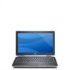
.... trackstick buttons (3) 18. device status lights Figure 2. network connector 2. security cable slot 5. Fan noise is running. 13. Secure Digital (SD) memory-card reader 15. Restricting the airflow can damage the computer or cause a fire. VGA connector 7. keyboard 20. Quick Setup WARNING: Before you begin...: Do not block, push objects into, or allow dust to accumulate in this section, read the safety information that shipped with your Dell computer in a low-airflow environment, such as a closed briefcase, while it is normal and does not indicate a problem with the fan...
.... trackstick buttons (3) 18. device status lights Figure 2. network connector 2. security cable slot 5. Fan noise is running. 13. Secure Digital (SD) memory-card reader 15. Restricting the airflow can damage the computer or cause a fire. VGA connector 7. keyboard 20. Quick Setup WARNING: Before you begin...: Do not block, push objects into, or allow dust to accumulate in this section, read the safety information that shipped with your Dell computer in a low-airflow environment, such as a closed briefcase, while it is normal and does not indicate a problem with the fan...
User Manual
Page 4
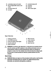
...Chipset Processor Mobile Intel QM67 Express Chipset Intel Core i3/i5/i7 series (2nd generation) Video Video type Data bus Video controller memory integrated on and shut down your computer. The following specifications are only those required by region. Specifications NOTE: Offerings may vary ...by law to ship with your computer at least once before you turn on system board integrated video 512 MB Memory Memory connector Memory capacity Memory type Minimum memory Maximum memory two SODIMM slots 1 GB, 2 GB, or 4 GB DDR3 SDRAM (1333 MHz) 1 GB 8 GB 4 For more ...
...Chipset Processor Mobile Intel QM67 Express Chipset Intel Core i3/i5/i7 series (2nd generation) Video Video type Data bus Video controller memory integrated on and shut down your computer. The following specifications are only those required by region. Specifications NOTE: Offerings may vary ...by law to ship with your computer at least once before you turn on system board integrated video 512 MB Memory Memory connector Memory capacity Memory type Minimum memory Maximum memory two SODIMM slots 1 GB, 2 GB, or 4 GB DDR3 SDRAM (1333 MHz) 1 GB 8 GB 4 For more ...
Owners Manual
Page 4
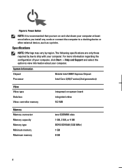
Installing The Optical Drive 25 8 Base Cover 27 Removing The Base Cover 27 Installing The Base Cover 28 9 Memory Card 29 Removing The Memory 29 Installing The Memory...30 10 Coin-Cell Battery 31 Removing The Coin-Cell Battery 31 Installing The Coin-Cell Battery 32 11 Wireless Local Area Network (WLAN) Card ...
Installing The Optical Drive 25 8 Base Cover 27 Removing The Base Cover 27 Installing The Base Cover 28 9 Memory Card 29 Removing The Memory 29 Installing The Memory...30 10 Coin-Cell Battery 31 Removing The Coin-Cell Battery 31 Installing The Coin-Cell Battery 32 11 Wireless Local Area Network (WLAN) Card ...

Owners Manual
Page 29
Follow the procedures in Before Working On Your Computer 2. Pry the retention clips away from the computer. 29 Remove the battery. 3. Remove the base cover. 5. Remove the memory module from the memory module until it pops up. 6. Memory Card 9 Removing The Memory 1. Remove the Secure Digital (SD) card. 4.
Follow the procedures in Before Working On Your Computer 2. Pry the retention clips away from the computer. 29 Remove the battery. 3. Remove the base cover. 5. Remove the memory module from the memory module until it pops up. 6. Memory Card 9 Removing The Memory 1. Remove the Secure Digital (SD) card. 4.
Owners Manual
Page 30
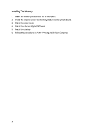
Install the base cover. 4. Installing The Memory 1. Follow the procedures in After Working Inside Your Computer. 30 Install the Secure Digital (SD) card. 5. Press the clips to secure the memory module to the system board. 3. Install the battery 6. Insert the memory module into the memory slot. 2.
Install the base cover. 4. Installing The Memory 1. Follow the procedures in After Working Inside Your Computer. 30 Install the Secure Digital (SD) card. 5. Press the clips to secure the memory module to the system board. 3. Install the battery 6. Insert the memory module into the memory slot. 2.
Owners Manual
Page 97
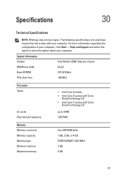
Specifications 30 Technical Specifications NOTE: Offerings may vary by law to 6 MB 1333 MHz Memory Memory connector Memory capacity Memory type Minimum memory Maximum memory two SODIMM slots 1 GB, 2 GB, or 4 GB DDR3 SDRAM (1333 MHz) 2 GB 8 GB 97 For more information regarding the configuration of your computer, click Start &#...
Specifications 30 Technical Specifications NOTE: Offerings may vary by law to 6 MB 1333 MHz Memory Memory connector Memory capacity Memory type Minimum memory Maximum memory two SODIMM slots 1 GB, 2 GB, or 4 GB DDR3 SDRAM (1333 MHz) 2 GB 8 GB 97 For more information regarding the configuration of your computer, click Start &#...
Owners Manual
Page 98
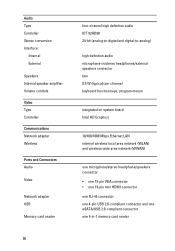
... conversion Interface: Internal External Speakers Internal speaker amplifier Volume controls Video Type Controller Communications Network adapter Wireless Ports and Connectors Audio Video Network adapter USB Memory card reader 98 four-channel high definition audio IDT 92HD90 24-bit (analog-to-digital and digital-to-analog) high definition audio microphone-in/stereo... connector • one 19-pin mini HDMI connector one RJ-45 connector one 4-pin USB 2.0-compliant connector and one eSATA/USB 2.0-compliant connector one 5-in-1 memory card reader
... conversion Interface: Internal External Speakers Internal speaker amplifier Volume controls Video Type Controller Communications Network adapter Wireless Ports and Connectors Audio Video Network adapter USB Memory card reader 98 four-channel high definition audio IDT 92HD90 24-bit (analog-to-digital and digital-to-analog) high definition audio microphone-in/stereo... connector • one 19-pin mini HDMI connector one RJ-45 connector one 4-pin USB 2.0-compliant connector and one eSATA/USB 2.0-compliant connector one 5-in-1 memory card reader
Owners Manual
Page 103
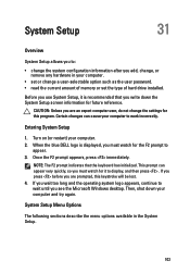
CAUTION: Unless you are prompted, this program. When the blue DELL logo is recommended that the keyboard has initialized. Once the F2 prompt appears, press immediately. Then, shut down the System Setup screen information for future ... indicates that you are an expert computer user, do not change a user-selectable option such as the user password. • read the current amount of memory or set the type of hard drive installed. This prompt can cause your computer to display, and then press . If you press before you write...
CAUTION: Unless you are prompted, this program. When the blue DELL logo is recommended that the keyboard has initialized. Once the F2 prompt appears, press immediately. Then, shut down the System Setup screen information for future ... indicates that you are an expert computer user, do not change a user-selectable option such as the user password. • read the current amount of memory or set the type of hard drive installed. This prompt can cause your computer to display, and then press . If you press before you write...
Owners Manual
Page 104
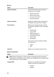
The options are : • Legacy • UEFI Date/Time Allows you to configure the integrated network controller. Depending on your computer. • System Information • Memory Information • Processor Information • Device Information Battery Information Boot Sequence Displays the battery status and the type of your computer and installed devices, the ...
The options are : • Legacy • UEFI Date/Time Allows you to configure the integrated network controller. Depending on your computer. • System Information • Memory Information • Processor Information • Device Information Battery Information Boot Sequence Displays the battery status and the type of your computer and installed devices, the ...
Owners Manual
Page 116
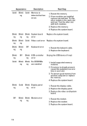
...Display panel ng ng error 1. Test the other module in each slot. 3. Blinki Blinki Solid Video card error Replace the system board. If memory is ng detected but has errors Next Step 1. Replace the video card/system board. Replace the keyboard. Off Blinki Blinki Modem error ng ng... ng ng error Solid Blinki Blinki No SODIMMs ng ng are installed remove one at a time in the same slot and test. Install supported memory modules. 2. Reseat the modem. 2. Replace the system board. Replace the modem. 3. Replace the display panel. 3. Replace the system board. Appearance...
...Display panel ng ng error 1. Test the other module in each slot. 3. Blinki Blinki Solid Video card error Replace the system board. If memory is ng detected but has errors Next Step 1. Replace the video card/system board. Replace the keyboard. Off Blinki Blinki Modem error ng ng... ng ng error Solid Blinki Blinki No SODIMMs ng ng are installed remove one at a time in the same slot and test. Install supported memory modules. 2. Reseat the modem. 2. Replace the system board. Replace the modem. 3. Replace the display panel. 3. Replace the system board. Appearance...


