User Manual
Page 1
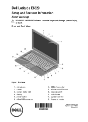
camera status light 4. USB 2.0 connector 8. volume control buttons 9. fingerprint reader Regulatory Model: P12S Regulatory Type: P12S001 February 2011 ExpressCard slot 12. eSata/USB connector 7. wireless switch 10. Front and Back View Figure 1. Dell Latitude E6320 Setup and Features Information About Warnings WARNING: A WARNING indicates a potential for property damage, personal injury, or death. display 5. optical drive 11. microphone 2. camera 3. Front view 1. power button 6.
camera status light 4. USB 2.0 connector 8. volume control buttons 9. fingerprint reader Regulatory Model: P12S Regulatory Type: P12S001 February 2011 ExpressCard slot 12. eSata/USB connector 7. wireless switch 10. Front and Back View Figure 1. Dell Latitude E6320 Setup and Features Information About Warnings WARNING: A WARNING indicates a potential for property damage, personal injury, or death. display 5. optical drive 11. microphone 2. camera 3. Front view 1. power button 6.
User Manual
Page 3
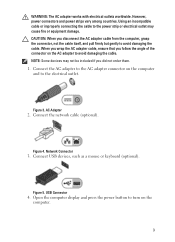
... power strips vary among countries. Connect the network cable (optional). Network Connector 3. Figure 4. NOTE: Some devices may cause fire or equipment damage. Open the computer display and press the power button to the power strip or electrical outlet may not be included if you disconnect the AC adapter cable from the...
... power strips vary among countries. Connect the network cable (optional). Network Connector 3. Figure 4. NOTE: Some devices may cause fire or equipment damage. Open the computer display and press the power button to the power strip or electrical outlet may not be included if you disconnect the AC adapter cable from the...
Owners Manual
Page 5
... 19 Media Board 57 Removing The Media Board 57 Installing The Media Board 59 20 Display Hinges 61 Removing The Display Hinge Covers 61 Installing The Display Hinge Covers 62 21 Display Assembly 63 Removing The Display Assembly 63 Installing The Display Assembly 67 22 System Board 69 Removing The System Board 69 Installing The System...
... 19 Media Board 57 Removing The Media Board 57 Installing The Media Board 59 20 Display Hinges 61 Removing The Display Hinge Covers 61 Installing The Display Hinge Covers 62 21 Display Assembly 63 Removing The Display Assembly 63 Installing The Display Assembly 67 22 System Board 69 Removing The System Board 69 Installing The System...
Owners Manual
Page 6
...-In Port 87 Removing The DC-In Port 87 Installing The DC-In Port 89 27 Display Bezel 91 Removing The Display Bezel 91 Installing The Display Bezel 92 28 Display Panel 93 Removing The Display Panel 93 Installing The Display Panel 94 29 Camera...95 Removing The Camera...95 Installing The Camera...96 30 Specifications...
...-In Port 87 Removing The DC-In Port 87 Installing The DC-In Port 89 27 Display Bezel 91 Removing The Display Bezel 91 Installing The Display Bezel 92 28 Display Panel 93 Removing The Display Panel 93 Installing The Display Panel 94 29 Camera...95 Removing The Camera...95 Installing The Camera...96 30 Specifications...
Owners Manual
Page 10
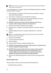
... steps before you work, periodically touch an unpainted metal surface to prevent the computer cover from the electrical outlet before opening the display. Disconnect your computer and then unplug the cable from their electrical outlets. 6. Remove any installed ExpressCards or Smart Cards from the...appear differently than shown in this document. Remove the main battery. 8. Turn off your computer from being scratched. 2. Close the display and turn the computer upside-down on a flat work surface is connected to ground the system board. To avoid damaging your computer...
... steps before you work, periodically touch an unpainted metal surface to prevent the computer cover from the electrical outlet before opening the display. Disconnect your computer and then unplug the cable from their electrical outlets. 6. Remove any installed ExpressCards or Smart Cards from the...appear differently than shown in this document. Remove the main battery. 8. Turn off your computer from being scratched. 2. Close the display and turn the computer upside-down on a flat work surface is connected to ground the system board. To avoid damaging your computer...
Owners Manual
Page 39
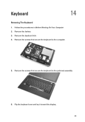
Remove the keyboard trim. 4. Remove the screws that secure the keyboard to the computer. 5. Keyboard 14 Removing The Keyboard 1. Remove the battery. 3. Remove the screws that secure the keyboard to the palmrest assembly. 6. Follow the procedures in Before Working On Your Computer. 2. Flip the keyboard over and lay it toward the display. 39
Remove the keyboard trim. 4. Remove the screws that secure the keyboard to the computer. 5. Keyboard 14 Removing The Keyboard 1. Remove the battery. 3. Remove the screws that secure the keyboard to the palmrest assembly. 6. Follow the procedures in Before Working On Your Computer. 2. Flip the keyboard over and lay it toward the display. 39
Owners Manual
Page 61
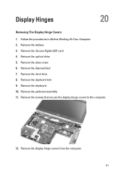
Remove the Secure Digital (SD) card. 4. Remove the optical drive. 5. Remove the keyboard trim. 9. Remove the ExpressCard. 7. Remove the display hinge covers from the computer. 61 Remove the base cover. 6. Follow the procedures in Before Working On Your Computer. 2. Remove the screws that secure the display hinge covers to the computer. 12. Remove the hard drive. 8. Remove the battery. 3. Remove the palmrest assembly. 11. Remove the keyboard. 10. Display Hinges 20 Removing The Display Hinge Covers 1.
Remove the Secure Digital (SD) card. 4. Remove the optical drive. 5. Remove the keyboard trim. 9. Remove the ExpressCard. 7. Remove the display hinge covers from the computer. 61 Remove the base cover. 6. Follow the procedures in Before Working On Your Computer. 2. Remove the screws that secure the display hinge covers to the computer. 12. Remove the hard drive. 8. Remove the battery. 3. Remove the palmrest assembly. 11. Remove the keyboard. 10. Display Hinges 20 Removing The Display Hinge Covers 1.
Owners Manual
Page 62
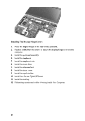
Install the hard drive. 7. Install the Secure Digital (SD) card. 11. Installing The Display Hinge Covers 1. Replace and tighten the screws to secure the display hinge covers to the computer. 3. Install the ExpressCard. 8. Install the keyboard. 5. Install the base cover. 9. Follow the procedures in the appropriate positions. 2. Install the optical drive. 10. Install the battery. 12. Install the keyboard trim. 6. Place the display hinges in After Working Inside Your Computer. 62 Install the palmrest assembly. 4.
Install the hard drive. 7. Install the Secure Digital (SD) card. 11. Installing The Display Hinge Covers 1. Replace and tighten the screws to secure the display hinge covers to the computer. 3. Install the ExpressCard. 8. Install the keyboard. 5. Install the base cover. 9. Follow the procedures in the appropriate positions. 2. Install the optical drive. 10. Install the battery. 12. Install the keyboard trim. 6. Place the display hinges in After Working Inside Your Computer. 62 Install the palmrest assembly. 4.
Owners Manual
Page 63
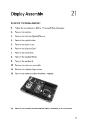
Remove the battery. 3. Remove the keyboard trim. 9. Release the antenna cables from the computer. 13. Remove the Secure Digital (SD) card. 4. Remove the ExpressCard. 7. Remove the palmrest assembly. 11. Remove the keyboard. 10. Remove the display hinge covers. 12. Remove the optical drive. 5. Remove the base cover. 6. Remove the hard drive. 8. Remove the screws that secure the display assembly to the computer. 63 Follow the procedures in Before Working On Your Computer. 2. Display Assembly 21 Removing The Display Assembly 1.
Remove the battery. 3. Remove the keyboard trim. 9. Release the antenna cables from the computer. 13. Remove the Secure Digital (SD) card. 4. Remove the ExpressCard. 7. Remove the palmrest assembly. 11. Remove the keyboard. 10. Remove the display hinge covers. 12. Remove the optical drive. 5. Remove the base cover. 6. Remove the hard drive. 8. Remove the screws that secure the display assembly to the computer. 63 Follow the procedures in Before Working On Your Computer. 2. Display Assembly 21 Removing The Display Assembly 1.

Owners Manual
Page 64
Pull out the antenna cables from their routing channels? 15. 14. Remove the screws that secure the display cable bracket to the system board. 64
Pull out the antenna cables from their routing channels? 15. 14. Remove the screws that secure the display cable bracket to the system board. 64

Owners Manual
Page 65
Pull the display cable to the computer. 65 16. Remove the display cable bracket from the system board. 18. Remove the screw that secures the display assembly to disconnect it from the computer. 17.
Pull the display cable to the computer. 65 16. Remove the display cable bracket from the system board. 18. Remove the screw that secures the display assembly to disconnect it from the computer. 17.

Owners Manual
Page 66
Remove the display assembly from the computer. 66 19.
Remove the display assembly from the computer. 66 19.

Owners Manual
Page 67
... the keyboard trim. 13. Install the hard drive. 14. Install the optical drive. 17. Install the battery. 19. Installing The Display Assembly 1. Replace and connect the display cable to the computer. 3. Install the base cover. 16. Install the Secure Digital (SD) card. 18. Align the.... 12. Install the ExpressCard. 15. Replace and tighten the screw to secure the display assembly to the system board. 4. Install the display hinge covers. 10. Replace and tighten the screws to secure the display panel to its original position on the computer. 2. Follow the procedures in After Working...
... the keyboard trim. 13. Install the hard drive. 14. Install the optical drive. 17. Install the battery. 19. Installing The Display Assembly 1. Replace and connect the display cable to the computer. 3. Install the base cover. 16. Install the Secure Digital (SD) card. 18. Align the.... 12. Install the ExpressCard. 15. Replace and tighten the screw to secure the display assembly to the system board. 4. Install the display hinge covers. 10. Replace and tighten the screws to secure the display panel to its original position on the computer. 2. Follow the procedures in After Working...
Owners Manual
Page 69
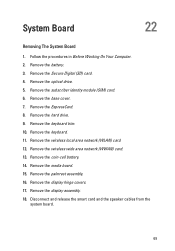
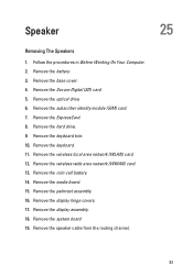
... the keyboard. 11. Remove the coin-cell battery. 14. Remove the base cover. 7. Remove the keyboard trim. 10. Remove the palmrest assembly. 16. Remove the display hinge covers. 17. Disconnect and release the smart card and the speaker cables from the system board. 69 Remove the wireless local area network (WLAN... ExpressCard. 8. Remove the wireless wide area network (WWAN) card. 13. Remove the hard drive. 9. Follow the procedures in Before Working On Your Computer. 2. Remove the display assembly. 18.
... the keyboard. 11. Remove the coin-cell battery. 14. Remove the base cover. 7. Remove the keyboard trim. 10. Remove the palmrest assembly. 16. Remove the display hinge covers. 17. Disconnect and release the smart card and the speaker cables from the system board. 69 Remove the wireless local area network (WLAN... ExpressCard. 8. Remove the wireless wide area network (WWAN) card. 13. Remove the hard drive. 9. Follow the procedures in Before Working On Your Computer. 2. Remove the display assembly. 18.

Owners Manual
Page 73
...screw to secure the TAA board to the computer. 6. Replace and tighten the screws to secure the system board to the computer. 3. Install the display assembly. 8. Install the ExpressCard. 14. Install the base cover. 15. Route and connect the smart card and speaker cables to the system board.... Align the system board into its original position on the computer. 4. Install the keyboard. 11. Install the optical drive. 16. Install the display hinge covers. 9. Install the palmrest assembly. 10. Install the keyboard trim. 12. Install the hard drive. 13. Install the battery. 18.
...screw to secure the TAA board to the computer. 6. Replace and tighten the screws to secure the system board to the computer. 3. Install the display assembly. 8. Install the ExpressCard. 14. Install the base cover. 15. Route and connect the smart card and speaker cables to the system board.... Align the system board into its original position on the computer. 4. Install the keyboard. 11. Install the optical drive. 16. Install the display hinge covers. 9. Install the palmrest assembly. 10. Install the keyboard trim. 12. Install the hard drive. 13. Install the battery. 18.
Owners Manual
Page 75
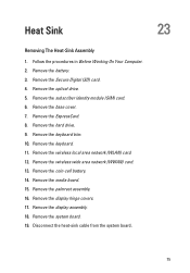
... keyboard trim. 10. Remove the wireless local area network (WLAN) card. 12. Remove the palmrest assembly. 16. Remove the hard drive. 9. Remove the display hinge covers. 17. Remove the display assembly. 18. Remove the subscriber identity module (SIM) card. 6. Remove the base cover. 7. Follow the procedures in Before Working On Your Computer...
... keyboard trim. 10. Remove the wireless local area network (WLAN) card. 12. Remove the palmrest assembly. 16. Remove the hard drive. 9. Remove the display hinge covers. 17. Remove the display assembly. 18. Remove the subscriber identity module (SIM) card. 6. Remove the base cover. 7. Follow the procedures in Before Working On Your Computer...

Owners Manual
Page 77
... the hard drive. 11. Install the optical drive. 14. Install the battery. 16. Follow the procedures in After Working Inside Your Computer. 77 Install the display hinge covers. 7. Installing The Heat-Sink Assembly 1. Connect the heat-sink cable to the system board. 3. Install the keyboard trim. 10. Install the ExpressCard. 12... assembly. 5. Install the palmrest assembly. 8. Install the base cover. 13. Align the heat-sink assembly to its original position on the system board. 2. Install the display assembly. 6. Install the Secure Digital (SD) card. 15.
... the hard drive. 11. Install the optical drive. 14. Install the battery. 16. Follow the procedures in After Working Inside Your Computer. 77 Install the display hinge covers. 7. Installing The Heat-Sink Assembly 1. Connect the heat-sink cable to the system board. 3. Install the keyboard trim. 10. Install the ExpressCard. 12... assembly. 5. Install the palmrest assembly. 8. Install the base cover. 13. Align the heat-sink assembly to its original position on the system board. 2. Install the display assembly. 6. Install the Secure Digital (SD) card. 15.
Owners Manual
Page 79
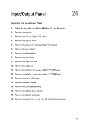
... that secures the I/O panel to the computer. 79 Remove the hard drive. 9. Remove the wireless local area network (WLAN) card. 12. Remove the display hinge covers. 17. Remove the display assembly. 18. Input/Output Panel 24 Removing The Input/Output Panel 1. Remove the Secure Digital (SD) card. 4. Remove the optical drive. 5. Remove...
... that secures the I/O panel to the computer. 79 Remove the hard drive. 9. Remove the wireless local area network (WLAN) card. 12. Remove the display hinge covers. 17. Remove the display assembly. 18. Input/Output Panel 24 Removing The Input/Output Panel 1. Remove the Secure Digital (SD) card. 4. Remove the optical drive. 5. Remove...
Owners Manual
Page 81
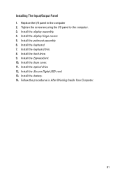
Replace the I /O panel to the computer. 3. Install the palmrest assembly. 6. Install the optical drive. 12. Installing The Input/Output Panel 1. Tighten the screw securing the I /O panel in After Working Inside Your Computer. 81 Follow the procedures in the computer 2. Install the keyboard. 7. Install the ExpressCard. 10. Install the battery. 14. Install the base cover. 11. Install the display assembly. 4. Install the display hinge covers. 5. Install the keyboard trim. 8. Install the hard drive. 9. Install the Secure Digital (SD) card. 13.
Replace the I /O panel to the computer. 3. Install the palmrest assembly. 6. Install the optical drive. 12. Installing The Input/Output Panel 1. Tighten the screw securing the I /O panel in After Working Inside Your Computer. 81 Follow the procedures in the computer 2. Install the keyboard. 7. Install the ExpressCard. 10. Install the battery. 14. Install the base cover. 11. Install the display assembly. 4. Install the display hinge covers. 5. Install the keyboard trim. 8. Install the hard drive. 9. Install the Secure Digital (SD) card. 13.
Owners Manual
Page 83
.... 18. Remove the system board 19. Remove the Secure Digital (SD) card. 5. Remove the optical drive. 6. Remove the display hinge covers. 17. Remove the wireless wide area network (WWAN) card. 13. Remove the ExpressCard. 8. Remove the keyboard trim. 10. Remove the keyboard. 11. Remove ...
.... 18. Remove the system board 19. Remove the Secure Digital (SD) card. 5. Remove the optical drive. 6. Remove the display hinge covers. 17. Remove the wireless wide area network (WWAN) card. 13. Remove the ExpressCard. 8. Remove the keyboard trim. 10. Remove the keyboard. 11. Remove ...


