
User Manual
Page 52
... Network adapter Wireless Ports and Connectors Audio (optional) Video Network adapter USB 2.0 USB 3.0 Memory card reader Docking port Subscriber Identity Module (SIM) port Display Type Latitude E5430 Latitude E5530 Size Latitude E5430 Latitude E5530 Dimensions: 52 1W (RMS) per channel keyboard function keys, ...15-pin VGA connector • 19-pin HDMI connector one RJ-45 connector • two 4-pin USB 2.0-compliant connector • One USB 3.0-compliant connector • One eSATA/USB 3.0-compliant connector one 8-in-1 memory card reader one one • HD(1366x768), WLED • ...
... Network adapter Wireless Ports and Connectors Audio (optional) Video Network adapter USB 2.0 USB 3.0 Memory card reader Docking port Subscriber Identity Module (SIM) port Display Type Latitude E5430 Latitude E5530 Size Latitude E5430 Latitude E5530 Dimensions: 52 1W (RMS) per channel keyboard function keys, ...15-pin VGA connector • 19-pin HDMI connector one RJ-45 connector • two 4-pin USB 2.0-compliant connector • One USB 3.0-compliant connector • One eSATA/USB 3.0-compliant connector one 8-in-1 memory card reader one one • HD(1366x768), WLED • ...
User Manual
Page 60
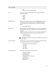
... Operation 60 Allows you to change the order in which the computer attempts to find an operating system. • Diskette Drive • Internal HDD • USB Storage Device • CD/DVD/CD-RW Drive • Onboard NIC Allows you to change the date and time. The options are : • Disabled •...
... Operation 60 Allows you to change the order in which the computer attempts to find an operating system. • Diskette Drive • Internal HDD • USB Storage Device • CD/DVD/CD-RW Drive • Onboard NIC Allows you to change the date and time. The options are : • Disabled •...
User Manual
Page 61
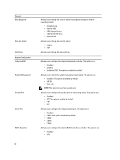
...startup. This option is enabled by default. This technology is enabled and available for integrated drives are enabled by default. If USB port is enabled, device attached to this port is part of the keyboard illumination feature. This field lets you choose the... operating mode of the SMART (Self Monitoring Analysis and Reporting Technology) specification. System Configuration Drives SMART Reporting USB Controller Keyboard Illumination Miscellaneous Devices • AHCI • RAID On: This option is disabled by default. • Enable SMART Reporting...
...startup. This option is enabled by default. This technology is enabled and available for integrated drives are enabled by default. If USB port is enabled, device attached to this port is part of the keyboard illumination feature. This field lets you choose the... operating mode of the SMART (Self Monitoring Analysis and Reporting Technology) specification. System Configuration Drives SMART Reporting USB Controller Keyboard Illumination Miscellaneous Devices • AHCI • RAID On: This option is disabled by default. • Enable SMART Reporting...

User Manual
Page 64
...to set the time at which the computer must turn on automatically. Performance Hyper-Thread Control Power Management AC Behavior Auto On Time USB Wake Support Wireless Radio Control Wake on LAN/WLAN Block Sleep Primary Battery Configuration Default Setting: Enable Intel TurboBoost Allows you block ...power adapter is removed during Standby, the system setup will remove power from all of the USB ports to conserve battery power. • Enable USB Wake Support • Default Setting: Enable USB Wake Support is not selected Allows you to enable or disable the feature that automatically switches ...
...to set the time at which the computer must turn on automatically. Performance Hyper-Thread Control Power Management AC Behavior Auto On Time USB Wake Support Wireless Radio Control Wake on LAN/WLAN Block Sleep Primary Battery Configuration Default Setting: Enable Intel TurboBoost Allows you block ...power adapter is removed during Standby, the system setup will remove power from all of the USB ports to conserve battery power. • Enable USB Wake Support • Default Setting: Enable USB Wake Support is not selected Allows you to enable or disable the feature that automatically switches ...
Setup and Features Information Tech Sheet
Page 2
...-drive eject button 12. touchpad buttons 18. Back View 1. security cable slot 6. Secure Digital (SD) memory-card slot 11. fingerprint reader (optional) 16. keyboard 23. USB 2.0 connector 3. eSATA/USB 3.0 connector 9. microphone 10. volume control buttons 11. touchpad 17. wireless switch 19. cooling vents 7. trackstick buttons (optional) 21. power connector...
...-drive eject button 12. touchpad buttons 18. Back View 1. security cable slot 6. Secure Digital (SD) memory-card slot 11. fingerprint reader (optional) 16. keyboard 23. USB 2.0 connector 3. eSATA/USB 3.0 connector 9. microphone 10. volume control buttons 11. touchpad 17. wireless switch 19. cooling vents 7. trackstick buttons (optional) 21. power connector...
Setup and Features Information Tech Sheet
Page 3
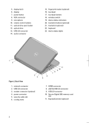
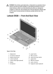
Front View 1. display latch 2. optical-drive eject button 11. Restricting the airflow can damage the computer or cause a fire. Latitude E5530 - display release latch 4. microphone 8. USB 2.0 connector 13. Do not store your Dell computer in the air vents. optical drive 12. audio connector 14. Fan noise is running. camera (optional) 5. VGA connector 10. fingerprint...
Front View 1. display latch 2. optical-drive eject button 11. Restricting the airflow can damage the computer or cause a fire. Latitude E5530 - display release latch 4. microphone 8. USB 2.0 connector 13. Do not store your Dell computer in the air vents. optical drive 12. audio connector 14. Fan noise is running. camera (optional) 5. VGA connector 10. fingerprint...
Setup and Features Information Tech Sheet
Page 4
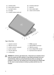
... View 1. network connector 2. Secure Digital (SD) card slot 11. touchpad buttons 18. USB 2.0 connector 3. Fan noise is running. volume control buttons Figure 4. power connector 5. cooling vents 7. USB 3.0 connector 10. Restricting the airflow can damage the computer or cause a fire. trackstick... (optional) 21. wireless switch 16. modem connector (optional) 4. device status indicators 17. Do not store your Dell computer in the air vents....
... View 1. network connector 2. Secure Digital (SD) card slot 11. touchpad buttons 18. USB 2.0 connector 3. Fan noise is running. volume control buttons Figure 4. power connector 5. cooling vents 7. USB 3.0 connector 10. Restricting the airflow can damage the computer or cause a fire. trackstick... (optional) 21. wireless switch 16. modem connector (optional) 4. device status indicators 17. Do not store your Dell computer in the air vents....
Setup and Features Information Tech Sheet
Page 5
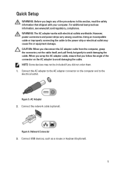
AC Adapter 2. Connect USB devices, such as a mouse or keyboard (optional). 5 For additional best practices information, see www.dell.com/regulatory_compliance. Using an incompatible cable or improperly connecting the cable to avoid damaging the cable. NOTE: Some devices may cause fire or equipment damage. ...
AC Adapter 2. Connect USB devices, such as a mouse or keyboard (optional). 5 For additional best practices information, see www.dell.com/regulatory_compliance. Using an incompatible cable or improperly connecting the cable to avoid damaging the cable. NOTE: Some devices may cause fire or equipment damage. ...
Setup and Features Information Tech Sheet
Page 6
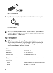
Figure 8. Power AC Adapter Input voltage Coin-cell battery 65 W and 90 W 100 VAC to 240 VAC 3 V CR2032 lithium coin cell Physical Latitude E5430 Height Width 29.9 mm to 32.5 mm (1.17 inches to view information about your computer. Specifications NOTE: Offerings may vary by law to a docking device ...; Help and Support and select the option to 1.27 inches) 350.00 mm (13.70 inches) 6 The following specifications are only those required by region. USB Connector 4. Figure 7.
Figure 8. Power AC Adapter Input voltage Coin-cell battery 65 W and 90 W 100 VAC to 240 VAC 3 V CR2032 lithium coin cell Physical Latitude E5430 Height Width 29.9 mm to 32.5 mm (1.17 inches to view information about your computer. Specifications NOTE: Offerings may vary by law to a docking device ...; Help and Support and select the option to 1.27 inches) 350.00 mm (13.70 inches) 6 The following specifications are only those required by region. USB Connector 4. Figure 7.


