Service Manual
Page 7
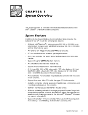
...in the modular bay. A CD-ROM drive for connecting external speakers or headphones, a microphone, and record/playback devices to 128 MB of the Dell® Latitude® CP and CPi portable computers. Support for up to the computer. Support for a zoom video PC Card in the modular bay. Software wavetable support and SRS 3-D...-burst SRAM external cache. A PC Card controller that increases system performance. This chapter provides an overview of the features and specifications of system memory. Support for 32-bit data transfer. When used with voice and music functions.
...in the modular bay. A CD-ROM drive for connecting external speakers or headphones, a microphone, and record/playback devices to 128 MB of the Dell® Latitude® CP and CPi portable computers. Support for up to the computer. Support for a zoom video PC Card in the modular bay. Software wavetable support and SRS 3-D...-burst SRAM external cache. A PC Card controller that increases system performance. This chapter provides an overview of the features and specifications of system memory. Support for 32-bit data transfer. When used with voice and music functions.
Service Manual
Page 8
A BIOS that resides in flash memory and that help you conserve battery power. display microphone power button keyboard touch pad battery bay touch pad buttons (2) modular bay display latch indicator panel cooling-fan air intake AC adapter connector audio jacks (3) speakers (2) 1-2 Dell Latitude CP and CPi Service Manual An infrared port compatible with two connectors that...
A BIOS that resides in flash memory and that help you conserve battery power. display microphone power button keyboard touch pad battery bay touch pad buttons (2) modular bay display latch indicator panel cooling-fan air intake AC adapter connector audio jacks (3) speakers (2) 1-2 Dell Latitude CP and CPi Service Manual An infrared port compatible with two connectors that...
Service Manual
Page 13
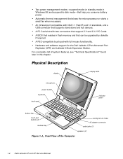
... MHz Bus architecture PCI Internal cache memory 32 KB External cache memory: Latitude CPi D300XT Latitude CPi D266XT Latitude CPi D233ST Latitude CP M233XT Latitude CP M233ST Latitude CP M233SD 512 KB pipelined-burst SRAM Latitude CP M166ST 256 KB pipelined-burst SRAM Math coprocessor internal to the microprocessor System chip set: Latitude CPi D300XT Latitude CPi D266XT Latitude CPi D233ST Intel 440BX PCIset Latitude CP M233XT Latitude CP M233ST Latitude CP M233SD Latitude CP M166ST Intel Mobile 430TX PCIset...
... MHz Bus architecture PCI Internal cache memory 32 KB External cache memory: Latitude CPi D300XT Latitude CPi D266XT Latitude CPi D233ST Latitude CP M233XT Latitude CP M233ST Latitude CP M233SD 512 KB pipelined-burst SRAM Latitude CP M166ST 256 KB pipelined-burst SRAM Math coprocessor internal to the microprocessor System chip set: Latitude CPi D300XT Latitude CPi D266XT Latitude CPi D233ST Intel 440BX PCIset Latitude CP M233XT Latitude CP M233ST Latitude CP M233SD Latitude CP M166ST Intel Mobile 430TX PCIset...
Service Manual
Page 14
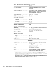
...Windows NT ® 4.0 operating system does not support zoom video. 2 The Latitude CP and CPi do not support memory modules from previous models of Dell portable computers, such as the Latitude XP, XPi, XPi CD, and LM. 1-8 Dell Latitude CP and CPi Service Manual PC Card controller Texas Instruments PCI1131 CardBus controller PC Card connectors two... type and capacities2 16-, 32-, and 64-MB 3.3-V EDO SODIMMs Standard RAM one 16-MB memory module or one 32-MB memory module Maximum RAM 128 MB Memory access time: tRAC 60 ns tCAC 15 ns BIOS address F000:0000-F000:FFFF Serial (DTE one 9-pin ...
...Windows NT ® 4.0 operating system does not support zoom video. 2 The Latitude CP and CPi do not support memory modules from previous models of Dell portable computers, such as the Latitude XP, XPi, XPi CD, and LM. 1-8 Dell Latitude CP and CPi Service Manual PC Card controller Texas Instruments PCI1131 CardBus controller PC Card connectors two... type and capacities2 16-, 32-, and 64-MB 3.3-V EDO SODIMMs Standard RAM one 16-MB memory module or one 32-MB memory module Maximum RAM 128 MB Memory access time: tRAC 60 ns tCAC 15 ns BIOS address F000:0000-F000:FFFF Serial (DTE one 9-pin ...
Service Manual
Page 20
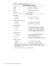
... to 35,000 ft) 6 Weight shown is with the hard-disk drive in the modular bay, and one memory module. Your computer might weigh more or less, depending on its configuration. 7 Measured with a hard-disk drive, a battery in the battery bay, a diskette drive in head-parked position. 1-14 Dell Latitude CP and CPi Service Manual
... to 35,000 ft) 6 Weight shown is with the hard-disk drive in the modular bay, and one memory module. Your computer might weigh more or less, depending on its configuration. 7 Measured with a hard-disk drive, a battery in the battery bay, a diskette drive in head-parked position. 1-14 Dell Latitude CP and CPi Service Manual
Service Manual
Page 26
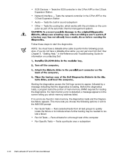
... the resources as necessary. For instructions, see Chapter 3, "Troubleshooting Your Computer," in the Reference and Troubleshooting Guide. 2-6 Dell Latitude CP and CPi Service Manual Resource conflicts can result in this chapter reveals the source of the problem or leads to two or more information...Troubleshooting Guide. Because devices may require dedicated memory spaces, interrupt levels, or DMA channels, all . Devices within the computer may be installed at all of which must be allocated during installation of the problem, call Dell for determining the source of the devices...
... the resources as necessary. For instructions, see Chapter 3, "Troubleshooting Your Computer," in the Reference and Troubleshooting Guide. 2-6 Dell Latitude CP and CPi Service Manual Resource conflicts can result in this chapter reveals the source of the problem or leads to two or more information...Troubleshooting Guide. Because devices may require dedicated memory spaces, interrupt levels, or DMA channels, all . Devices within the computer may be installed at all of which must be allocated during installation of the problem, call Dell for determining the source of the devices...
Service Manual
Page 28
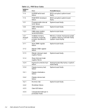
... failure Gate A20 failure Unexpected interrupt in protected mode 3-2 Dell Latitude CP and CPi Service Manual system board faulty BIOS corrupted; 1-1-3 1-1-4 1-2-1 1-2-2 1-2-3 1-3-1 through 1-1-1 3-1-1 3-1-2 3-1-3 3-1-4 3-2-4 3-3-4 3-4-1 3-4-2 4-2-1 4-2-2 4-2-3 4-2-4 NVRAM write/read failure ROM BIOS checksum failure Programmable interval timer failure DMA initialization failure DMA page register write/read failure Installed memory module(s) not being properly identified or used Slave DMA register...
... failure Gate A20 failure Unexpected interrupt in protected mode 3-2 Dell Latitude CP and CPi Service Manual system board faulty BIOS corrupted; 1-1-3 1-1-4 1-2-1 1-2-2 1-2-3 1-3-1 through 1-1-1 3-1-1 3-1-2 3-1-3 3-1-4 3-2-4 3-3-4 3-4-1 3-4-2 4-2-1 4-2-2 4-2-3 4-2-4 NVRAM write/read failure ROM BIOS checksum failure Programmable interval timer failure DMA initialization failure DMA page register write/read failure Installed memory module(s) not being properly identified or used Slave DMA register...

Service Manual
Page 32
...board faulty. Hard-disk drive faulty. 3-6 Dell Latitude CP and CPi Service Manual Defective or unformatted diskette. System board faulty. Amount of memory recorded in NVRAM does not match memory installed in the diskette drive. One or more memory modules faulty or improperly seated. The CD.... Diskette writeprotected. System board faulty. The diskette may be completed. Computer cannot enable protective mode. One or more memory modules faulty or improperly seated. Hard-disk drive or controller not responding to commands from computer. Message indicates system failure...
...board faulty. Hard-disk drive faulty. 3-6 Dell Latitude CP and CPi Service Manual Defective or unformatted diskette. System board faulty. Amount of memory recorded in NVRAM does not match memory installed in the diskette drive. One or more memory modules faulty or improperly seated. The CD.... Diskette writeprotected. System board faulty. The diskette may be completed. Computer cannot enable protective mode. One or more memory modules faulty or improperly seated. Hard-disk drive or controller not responding to commands from computer. Message indicates system failure...

Service Manual
Page 34
... Bad sector or corrupted FAT on hard-disk drive or diskette. Memory double word logic failure at address, read value expecting value Memory odd/even logic failure at address, read value expecting value Memory write/read failure at address, read value expecting value No boot...ROM in external device faulty. Optional ROM in external device failed. Installed memory module faulty or improperly seated. System board faulty. No operating system files on diskette or hard-disk drive. 3-8 Dell Latitude CP and CPi Service Manual MS-DOS® unable to locate a sector on harddisk ...
... Bad sector or corrupted FAT on hard-disk drive or diskette. Memory double word logic failure at address, read value expecting value Memory odd/even logic failure at address, read value expecting value Memory write/read failure at address, read value expecting value No boot...ROM in external device faulty. Optional ROM in external device failed. Installed memory module faulty or improperly seated. System board faulty. No operating system files on diskette or hard-disk drive. 3-8 Dell Latitude CP and CPi Service Manual MS-DOS® unable to locate a sector on harddisk ...
Service Manual
Page 36
... 5, "Getting Help," in the Reference and Troubleshooting Guide for loading the diagnostics. If a main memory error is loading. Tests a particular area or subsystem 3-10 Dell Latitude CP and CPi Service Manual NOTE: You must have a diskette-drive cable, you which works with the air intake... on contacting Dell. Starting the diagnostics causes the Dell logo screen to appear, followed by a message indicating...
... 5, "Getting Help," in the Reference and Troubleshooting Guide for loading the diagnostics. If a main memory error is loading. Tests a particular area or subsystem 3-10 Dell Latitude CP and CPi Service Manual NOTE: You must have a diskette-drive cable, you which works with the air intake... on contacting Dell. Starting the diagnostics causes the Dell logo screen to appear, followed by a message indicating...
Service Manual
Page 52
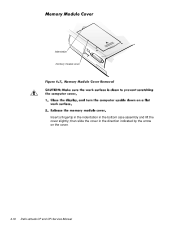
then slide the cover in the bottom case assembly and lift the cover slightly; indentation memory module cover Insert a fingertip in the indentation in the direction indicated by the arrow on the cover. 4-16 Dell Latitude CP and CPi Service Manual
then slide the cover in the bottom case assembly and lift the cover slightly; indentation memory module cover Insert a fingertip in the indentation in the direction indicated by the arrow on the cover. 4-16 Dell Latitude CP and CPi Service Manual
Service Manual
Page 90
... removal, 4-18 keyboard indicators, 1-5 LCD display hinge removal, 4-38 LCD inverter board removal, 4-35, 4-36 2 Dell Latitude CP and CPi Service Manual LCD panel removal, 4-31, 4-32 LEDs, 1-4 low-battery warnings, 1-4 main battery assembly removal, 4-3 memory module removal, 4-17 memory module cover removal, 4-16 messages, system error about, 3-5 list of, 3-5 modular bay devices removal, 4-42 module...
... removal, 4-18 keyboard indicators, 1-5 LCD display hinge removal, 4-38 LCD inverter board removal, 4-35, 4-36 2 Dell Latitude CP and CPi Service Manual LCD panel removal, 4-31, 4-32 LEDs, 1-4 low-battery warnings, 1-4 main battery assembly removal, 4-3 memory module removal, 4-17 memory module cover removal, 4-16 messages, system error about, 3-5 list of, 3-5 modular bay devices removal, 4-42 module...

Replacement Instructions
Page 17
... kit, memory door SVC,SUBASSY,DOOR, 7 assembly MEM/BIOS,CP Memory/BIOS door subassembly SUBASSY,DOOR, MEM/BIOS,NB,CP Touch-pad bracket Air flow duct BRCKT,TPAD,CP 13 GDE,INTK,AIR,FAN,PLSTC,CP 30 Service kit, palmrest SVC,SUBASSY,PLMRST,CP 12 assembly... Palmrest assembly ASSY,PLMRST,GRY,CP Power button SWT,PWR SW, CP Power button spring SPR,PWR SW,CP Dell Latitude CP and CPi...
... kit, memory door SVC,SUBASSY,DOOR, 7 assembly MEM/BIOS,CP Memory/BIOS door subassembly SUBASSY,DOOR, MEM/BIOS,NB,CP Touch-pad bracket Air flow duct BRCKT,TPAD,CP 13 GDE,INTK,AIR,FAN,PLSTC,CP 30 Service kit, palmrest SVC,SUBASSY,PLMRST,CP 12 assembly... Palmrest assembly ASSY,PLMRST,GRY,CP Power button SWT,PWR SW, CP Power button spring SPR,PWR SW,CP Dell Latitude CP and CPi...

Replacement Instructions
Page 22
Parts Removal and Replacement Guide Insert a fingertip in the indentation in the direction indicated by the arrow on a flat work surface. 2. then slide the cover in the bottom case assembly and lift the cover slightly; Close the display, and turn the computer upside down on the cover. 16 Dell Latitude CP and CPi - Release the memory module cover. indentation memory module cover 1.
Parts Removal and Replacement Guide Insert a fingertip in the indentation in the direction indicated by the arrow on a flat work surface. 2. then slide the cover in the bottom case assembly and lift the cover slightly; Close the display, and turn the computer upside down on the cover. 16 Dell Latitude CP and CPi - Release the memory module cover. indentation memory module cover 1.
Replacement Instructions
Page 23
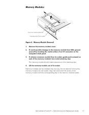
...of an I/O connector on each of the memory module with the corresponding key in the memory module socket. The memory module should rotate upward out of its socket, gently push outward on the computer's back panel. 3. Memory modules can be installed only one way. ...Align the notch near the center of the memory module's two metal retaining clips. Parts Removal and Replacement Guide 17 To avoid possible damage to force the memory module into the socket. Dell Latitude CP and CPi - memory module sockets (2) ...
...of an I/O connector on each of the memory module with the corresponding key in the memory module socket. The memory module should rotate upward out of its socket, gently push outward on the computer's back panel. 3. Memory modules can be installed only one way. ...Align the notch near the center of the memory module's two metal retaining clips. Parts Removal and Replacement Guide 17 To avoid possible damage to force the memory module into the socket. Dell Latitude CP and CPi - memory module sockets (2) ...
Replacement Instructions
Page 52
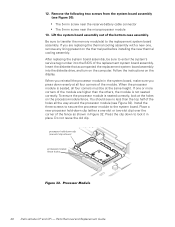
If you press down clip (either a one -slot clip shown) processor-module fence holes 46 Dell Latitude CP and CPi - Follow the instructions on the computer. Insert the diskette that accompanied the replacement system board assembly into the BIOS of the replacement system board assembly. ... the replacement system board assembly. processor hold -down evenly at all the way around the processor module (see Figure 32). Be sure to transfer the memory module(s) to lock it in Figure 32. Press the clip down clip (one -slot or two-slot clip) over the corner of the module. ...
If you press down clip (either a one -slot clip shown) processor-module fence holes 46 Dell Latitude CP and CPi - Follow the instructions on the computer. Insert the diskette that accompanied the replacement system board assembly into the BIOS of the replacement system board assembly. ... the replacement system board assembly. processor hold -down evenly at all the way around the processor module (see Figure 32). Be sure to transfer the memory module(s) to lock it in Figure 32. Press the clip down clip (one -slot or two-slot clip) over the corner of the module. ...

