Service Manual
Page 16
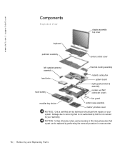
...by performing the removal procedure in this manual assumes that a part can be replaced by your system. www.dell.com | support.dell.com Components Exploded View display-assembly top cover keyboard palmrest assembly center control cover left speaker/antenna assembly hard ...drive main battery thermal cooling assembly hybrid cooling fan system board right speaker/antenna assembly modem and NIC connector covers fan guard modular...
...by performing the removal procedure in this manual assumes that a part can be replaced by your system. www.dell.com | support.dell.com Components Exploded View display-assembly top cover keyboard palmrest assembly center control cover left speaker/antenna assembly hard ...drive main battery thermal cooling assembly hybrid cooling fan system board right speaker/antenna assembly modem and NIC connector covers fan guard modular...
Service Manual
Page 20
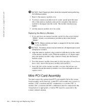
NOTE: Memory modules are keyed, or designed to fit into the bottom case assembly. www.dell.com | support.dell.com NOTICE: Read "Preparing to Work Inside the Computer" before the system board assembly can be connected to avoid damaging the connector. 2 Align the ...system's internal antenna. 20 Removi ng and Replacing Parts The module should pop up slightly. 3 Lift the memory module out of a modem, a NIC, a modem and NIC combination, or a wireless NIC. Install a second memory module in the center of the memory module socket just far enough for the memory module to the wiring harness...
NOTE: Memory modules are keyed, or designed to fit into the bottom case assembly. www.dell.com | support.dell.com NOTICE: Read "Preparing to Work Inside the Computer" before the system board assembly can be connected to avoid damaging the connector. 2 Align the ...system's internal antenna. 20 Removi ng and Replacing Parts The module should pop up slightly. 3 Lift the memory module out of a modem, a NIC, a modem and NIC combination, or a wireless NIC. Install a second memory module in the center of the memory module socket just far enough for the memory module to the wiring harness...
Service Manual
Page 21
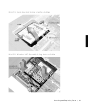
Mini-PCI Card Assembly Using Interface Cables socket modem connector NIC connector Mini PCI Wireless NIC Assembly Using Antenna Cable connection to internal antenna mini-coax antenna cable Removing and Repl aci ng Part s 21
Mini-PCI Card Assembly Using Interface Cables socket modem connector NIC connector Mini PCI Wireless NIC Assembly Using Antenna Cable connection to internal antenna mini-coax antenna cable Removing and Repl aci ng Part s 21
Service Manual
Page 22
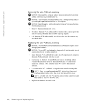
...or designed to avoid damaging the connector. Do not force the connection. 1 Align the mini-PCI card with the cover. place the unused NIC connector under the mini-PCI card. 4 Replace the memory module cover. 22 Removi ng and Replacing Parts Replacing the Mini-PCI Card Assembly ...1 Remove the memory module cover. 2 To release the mini-PCI card assembly from electrical outlets, and remove any installed batteries. www.dell.com | support.dell.com Removing the Mini-PCI Card Assembly NOTICE: Disconnect the computer and any attached devices from its socket, spread apart the metal securing ...
...or designed to avoid damaging the connector. Do not force the connection. 1 Align the mini-PCI card with the cover. place the unused NIC connector under the mini-PCI card. 4 Replace the memory module cover. 22 Removi ng and Replacing Parts Replacing the Mini-PCI Card Assembly ...1 Remove the memory module cover. 2 To release the mini-PCI card assembly from electrical outlets, and remove any installed batteries. www.dell.com | support.dell.com Removing the Mini-PCI Card Assembly NOTICE: Disconnect the computer and any attached devices from its socket, spread apart the metal securing ...

