Service Manual
Page 5
... Modules 20 Mini-PCI Card Assembly 20 Removing the Mini-PCI Card Assembly 22 Replacing the Mini-PCI Card Assembly 22 Keyboard Assembly 23 Removing the Keyboard Assembly 23 Replacing the Keyboard Assembly 25 Removing the Display Assembly 26 Removing the 14.1-Inch Display Assembly Bezel 30 Removing the 14.1-Inch Display Panel...
... Modules 20 Mini-PCI Card Assembly 20 Removing the Mini-PCI Card Assembly 22 Replacing the Mini-PCI Card Assembly 22 Keyboard Assembly 23 Removing the Keyboard Assembly 23 Replacing the Keyboard Assembly 25 Removing the Display Assembly 26 Removing the 14.1-Inch Display Assembly Bezel 30 Removing the 14.1-Inch Display Panel...
Service Manual
Page 12
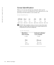
Screw Identification NOTICE: When reinstalling a screw, you are removing and replacing components, photocopy the placemat as a tool to Bottom Case Assembly: (5 each) 12 Be fo r e Yo u Be g in Screw Placement Hard Drive Door Security: (1 each) Keyboard to lay out and keep track of the component screws. www.dell.com | support.dell.com Screw Identification When you must use a screw of the correct diameter and length. The placemat provides the number of screws and the sizes. Make sure that the screw is properly aligned with its corresponding hole, and avoid overtightening.
Screw Identification NOTICE: When reinstalling a screw, you are removing and replacing components, photocopy the placemat as a tool to Bottom Case Assembly: (5 each) 12 Be fo r e Yo u Be g in Screw Placement Hard Drive Door Security: (1 each) Keyboard to lay out and keep track of the component screws. www.dell.com | support.dell.com Screw Identification When you must use a screw of the correct diameter and length. The placemat provides the number of screws and the sizes. Make sure that the screw is properly aligned with its corresponding hole, and avoid overtightening.
Service Manual
Page 15
SECTION 2 Removing and Replacing Parts Components Hard Drive Memory Module Mini-PCI Card Assembly Keyboard Assembly Removing the Display Assembly Display Assembly Latch Hinge Covers Palmrest Assembly Microprocessor Thermal Cooling Assembly Hybrid Cooling Fan Microprocessor Module Reserve Battery Speaker Assemblies System Board Assembly Battery and Modular Bay Latch Assemblies www.dell.com | support.dell.com
SECTION 2 Removing and Replacing Parts Components Hard Drive Memory Module Mini-PCI Card Assembly Keyboard Assembly Removing the Display Assembly Display Assembly Latch Hinge Covers Palmrest Assembly Microprocessor Thermal Cooling Assembly Hybrid Cooling Fan Microprocessor Module Reserve Battery Speaker Assemblies System Board Assembly Battery and Modular Bay Latch Assemblies www.dell.com | support.dell.com
Service Manual
Page 16
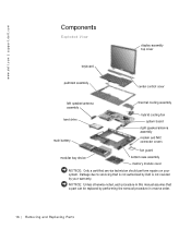
... order. 16 Removi ng and Replacing Parts Damage due to servicing that a part can be replaced by your system. www.dell.com | support.dell.com Components Exploded View display-assembly top cover keyboard palmrest assembly center control cover left speaker/antenna assembly hard drive main battery thermal cooling assembly hybrid cooling fan system...
... order. 16 Removi ng and Replacing Parts Damage due to servicing that a part can be replaced by your system. www.dell.com | support.dell.com Components Exploded View display-assembly top cover keyboard palmrest assembly center control cover left speaker/antenna assembly hard drive main battery thermal cooling assembly hybrid cooling fan system...
Service Manual
Page 19
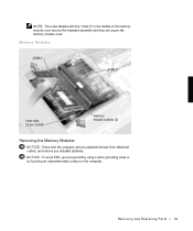
Removing and Repl aci ng Part s 19 NOTE: The screw labeled with the "circle K" in the middle of the memory module cover secures the keyboard assembly and does not secure the memory module cover. NOTICE: To avoid ESD, ground yourself by using a wrist grounding strap or by touching an unpainted metal surface on the computer. Memory Modules JDIM 1 JDIM 2 inner tabs (2 per socket) memory module sockets (2) Removing the Memory Modules NOTICE: Disconnect the computer and any attached devices from electrical outlets, and remove any installed batteries.
Removing and Repl aci ng Part s 19 NOTE: The screw labeled with the "circle K" in the middle of the memory module cover secures the keyboard assembly and does not secure the memory module cover. NOTICE: To avoid ESD, ground yourself by using a wrist grounding strap or by touching an unpainted metal surface on the computer. Memory Modules JDIM 1 JDIM 2 inner tabs (2 per socket) memory module sockets (2) Removing the Memory Modules NOTICE: Disconnect the computer and any attached devices from electrical outlets, and remove any installed batteries.

Service Manual
Page 23
... 23 NOTICE: To avoid ESD, ground yourself by using a wrist grounding strap or by touching an unpainted metal surface on the keyboard are fragile, easily dislodged, and time-consuming to Work Inside the Computer" before performing the following procedure. 1 Remove the hard ...and open the display. NOTICE: Read "Preparing to replace. Be careful when removing and handling the keyboard. NOTICE: The key caps on the computer. Keyboard Assembly Removing the Keyboard Screws M2.5 x 12-mm screws (5) Removing the Keyboard Assembly NOTICE: Disconnect the computer and any installed batteries.
... 23 NOTICE: To avoid ESD, ground yourself by using a wrist grounding strap or by touching an unpainted metal surface on the keyboard are fragile, easily dislodged, and time-consuming to Work Inside the Computer" before performing the following procedure. 1 Remove the hard ...and open the display. NOTICE: Read "Preparing to replace. Be careful when removing and handling the keyboard. NOTICE: The key caps on the computer. Keyboard Assembly Removing the Keyboard Screws M2.5 x 12-mm screws (5) Removing the Keyboard Assembly NOTICE: Disconnect the computer and any installed batteries.
Service Manual
Page 24
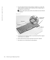
... the blank key on the palmrest. 24 Removi ng and Replacing Parts Keyboard track stick keyboard scalloped edge of blank key palmrest 5 Lift the keyboard straight up on the scalloped edge of the keyboard on the keyboard. www.dell.com | support.dell.com 4 To release the keyboard from the palmrest assembly, use a small, flatblade screwdriver or plastic scribe...
... the blank key on the palmrest. 24 Removi ng and Replacing Parts Keyboard track stick keyboard scalloped edge of blank key palmrest 5 Lift the keyboard straight up on the scalloped edge of the keyboard on the keyboard. www.dell.com | support.dell.com 4 To release the keyboard from the palmrest assembly, use a small, flatblade screwdriver or plastic scribe...
Service Manual
Page 25
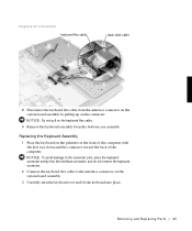
...and Repl aci ng Part s 25 Replacing the Keyboard Assembly 1 Place the keyboard on the system board assembly. 3 Carefully turn the keyboard over and fit the keyboard into place. NOTICE: Do not pull on the keyboard flex cable. 9 Remove the keyboard assembly from the interface connector on the system board ... up on the connector. NOTICE: To avoid damage to the connector pins, press the keyboard connector evenly into the interface connector, and do not reverse the keyboard connector. 2 Connect the keyboard flex cable to the interface connector on the palmrest at the front of the computer with...
...and Repl aci ng Part s 25 Replacing the Keyboard Assembly 1 Place the keyboard on the system board assembly. 3 Carefully turn the keyboard over and fit the keyboard into place. NOTICE: Do not pull on the keyboard flex cable. 9 Remove the keyboard assembly from the interface connector on the system board ... up on the connector. NOTICE: To avoid damage to the connector pins, press the keyboard connector evenly into the interface connector, and do not reverse the keyboard connector. 2 Connect the keyboard flex cable to the interface connector on the palmrest at the front of the computer with...
Service Manual
Page 26
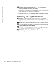
.... NOTICE: To avoid ESD, ground yourself by using a wrist grounding strap or by touching an unpainted metal surface on the computer. www.dell.com | support.dell.com NOTICE: Position the keyboard flex cable so it is not pinched when you remove the palmrest assembly; the display assembly hinges pass through the back of...
.... NOTICE: To avoid ESD, ground yourself by using a wrist grounding strap or by touching an unpainted metal surface on the computer. www.dell.com | support.dell.com NOTICE: Position the keyboard flex cable so it is not pinched when you remove the palmrest assembly; the display assembly hinges pass through the back of...
Service Manual
Page 42
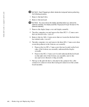
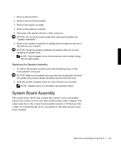
NOTICE: You must remove the display assembly before performing the following procedure. 1 Remove the hard drive. 2 Remove the keyboard. www.dell.com | support.dell.com NOTICE: Read "Preparing to remove it from the touch pad connector on the pull tab that is attached to the palmrest flex cable...are located on the back edge of the bottom case assembly, underneath the display assembly. • Remove the M2 x 3-mm screw located underneath the keyboard, on the right side of the bottom case assembly, next to the microprocessor thermal cooling assembly. 7 Pull up on the system board assembly. 42 ...
NOTICE: You must remove the display assembly before performing the following procedure. 1 Remove the hard drive. 2 Remove the keyboard. www.dell.com | support.dell.com NOTICE: Read "Preparing to remove it from the touch pad connector on the pull tab that is attached to the palmrest flex cable...are located on the back edge of the bottom case assembly, underneath the display assembly. • Remove the M2 x 3-mm screw located underneath the keyboard, on the right side of the bottom case assembly, next to the microprocessor thermal cooling assembly. 7 Pull up on the system board assembly. 42 ...
Service Manual
Page 44
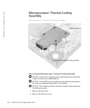
NOTICE: Read "Preparing to Work Inside the Computer" before performing the following procedure. 1 Remove the hard drive. 2 Remove the keyboard screws. 44 Removi ng and Replacing Parts www.dell.com | support.dell.com Microprocessor Thermal Cooling Assembly Microprocessor Thermal Cooling Assembly captive screws (4) microprocessor thermal cooling assembly Removing the Microprocessor Thermal Cooling Assembly NOTICE...
NOTICE: Read "Preparing to Work Inside the Computer" before performing the following procedure. 1 Remove the hard drive. 2 Remove the keyboard screws. 44 Removi ng and Replacing Parts www.dell.com | support.dell.com Microprocessor Thermal Cooling Assembly Microprocessor Thermal Cooling Assembly captive screws (4) microprocessor thermal cooling assembly Removing the Microprocessor Thermal Cooling Assembly NOTICE...
Service Manual
Page 45
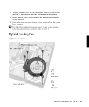
NOTICE: When reattaching the microprocessor thermal cooling assembly, tighten the captive screws in consecutive order, from the system board assembly. 3 Turn the computer over, lift the keyboard up, rotate it forward toward the front of the computer, and place it face down on the palmrest. 4 Loosen the four captive screws securing the microprocessor thermal cooling assembly. 5 Remove the microprocessor thermal cooling assembly from 1 to 4. Hybrid Cooling Fan Hybrid Cooling Fan M2.5 x 5-mm screws (2) M2 x 3-mm screw (1) hybrid cooling fan Removing and Repl aci ng Part s 45
NOTICE: When reattaching the microprocessor thermal cooling assembly, tighten the captive screws in consecutive order, from the system board assembly. 3 Turn the computer over, lift the keyboard up, rotate it forward toward the front of the computer, and place it face down on the palmrest. 4 Loosen the four captive screws securing the microprocessor thermal cooling assembly. 5 Remove the microprocessor thermal cooling assembly from 1 to 4. Hybrid Cooling Fan Hybrid Cooling Fan M2.5 x 5-mm screws (2) M2 x 3-mm screw (1) hybrid cooling fan Removing and Repl aci ng Part s 45
Service Manual
Page 46
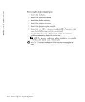
... hole when reinserting the fan cable. 46 Removi ng and Replacing Parts www.dell.com | support.dell.com Removing the Hybrid Cooling Fan 1 Remove the hard drive. 2 Remove the keyboard assembly. 3 Remove the display assembly. 4 Remove the palmrest assembly. 5 Remove the thermal cooling assembly. 6 Remove the two M2.5 x 5-mm screws and one M2...
... hole when reinserting the fan cable. 46 Removi ng and Replacing Parts www.dell.com | support.dell.com Removing the Hybrid Cooling Fan 1 Remove the hard drive. 2 Remove the keyboard assembly. 3 Remove the display assembly. 4 Remove the palmrest assembly. 5 Remove the thermal cooling assembly. 6 Remove the two M2.5 x 5-mm screws and one M2...

Service Manual
Page 47
...: Hold the microprocessor down while turning the cam screw to Work Inside the Computer" before performing the following procedure. 1 Remove the hard drive. 2 Remove the keyboard assembly.
...: Hold the microprocessor down while turning the cam screw to Work Inside the Computer" before performing the following procedure. 1 Remove the hard drive. 2 Remove the keyboard assembly.
Service Manual
Page 53
... speaker assemblies by pulling them straight up and out of the computer. Removing and Repl aci ng Part s 53 1 Remove the hard drive. 2 Remove the keyboard assembly. 3 Remove the display assembly. 4 Remove the palmrest assembly. 5 Disconnect the speaker interface cable connectors.
... speaker assemblies by pulling them straight up and out of the computer. Removing and Repl aci ng Part s 53 1 Remove the hard drive. 2 Remove the keyboard assembly. 3 Remove the display assembly. 4 Remove the palmrest assembly. 5 Disconnect the speaker interface cable connectors.
Service Manual
Page 54
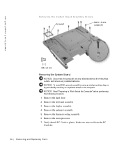
...the computer. NOTICE: Read "Preparing to Work Inside the Computer" before performing the following procedure. 1 Remove the hard drive. 2 Remove the keyboard assembly. 3 Remove the display assembly. 4 Remove the palmrest assembly. 5 Remove the thermal cooling assembly. 6 Remove the microprocessor. 7 Verify ...that all PC Cards or plastic blanks are removed from electrical outlets, and remove any installed batteries. www.dell.com | support.dell.com Removing the System Board Assembly Screws fan guard M2.5 x 5-mm screws (9) Removing the System Board NOTICE: Disconnect the...
...the computer. NOTICE: Read "Preparing to Work Inside the Computer" before performing the following procedure. 1 Remove the hard drive. 2 Remove the keyboard assembly. 3 Remove the display assembly. 4 Remove the palmrest assembly. 5 Remove the thermal cooling assembly. 6 Remove the microprocessor. 7 Verify ...that all PC Cards or plastic blanks are removed from electrical outlets, and remove any installed batteries. www.dell.com | support.dell.com Removing the System Board Assembly Screws fan guard M2.5 x 5-mm screws (9) Removing the System Board NOTICE: Disconnect the...
Service Manual
Page 56
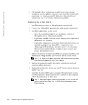
... and headphone connectors through the plastic bottom case assembly. b Replace the nine M2.5 x 5-mm screws, starting on the computer. www.dell.com | support.dell.com 13 Pull the right side of bottom case assembly, next to the external headphone and microphone connectors, away from the system board assembly...system board assembly, be crimped or pinched when the complete assembly is put back together. 5 Replace the palmrest assembly, the display assembly, the keyboard assembly, and the hard drive. 6 Replace the modular bay devices and any PC Cards or plastic blanks in the PC Card slot. 7 ...
... and headphone connectors through the plastic bottom case assembly. b Replace the nine M2.5 x 5-mm screws, starting on the computer. www.dell.com | support.dell.com 13 Pull the right side of bottom case assembly, next to the external headphone and microphone connectors, away from the system board assembly...system board assembly, be crimped or pinched when the complete assembly is put back together. 5 Replace the palmrest assembly, the display assembly, the keyboard assembly, and the hard drive. 6 Replace the modular bay devices and any PC Cards or plastic blanks in the PC Card slot. 7 ...

Service Manual
Page 58
...bottom of the case. If the latch assembly does come loose from the bottom case assembly by squeezing the snap tabs. www.dell.com | support.dell.com NOTICE: Read "Preparing to prevent the latch assembly from coming loose from the bottom of the base, making certain the ...the latch and spring while unsnapping the snap tabs to Work Inside the Computer" before performing the following procedure. 1 Remove the hard drive. 2 Remove the keyboard assembly. 3 Remove the display assembly. 4 Remove the palmrest assembly. 5 Remove the system board. 6 Remove the battery latch button from the case: a...
...bottom of the case. If the latch assembly does come loose from the bottom case assembly by squeezing the snap tabs. www.dell.com | support.dell.com NOTICE: Read "Preparing to prevent the latch assembly from coming loose from the bottom of the base, making certain the ...the latch and spring while unsnapping the snap tabs to Work Inside the Computer" before performing the following procedure. 1 Remove the hard drive. 2 Remove the keyboard assembly. 3 Remove the display assembly. 4 Remove the palmrest assembly. 5 Remove the system board. 6 Remove the battery latch button from the case: a...
Service Manual
Page 59
... cover replacing, 35 display-feed flex cable H hard drive, 17 removing, 17 replacing, 17 hinge covers removing, 39 replacing, 40 hybrid cooling fan removing, 46 K keyboard, 23 removing, 23 replacing, 25 M memory module, 18 removing, 19 replacing, 20 microprocessor module removing, 47 replacing, 48 microprocessor thermal cooling assembly removing, 44 mini...
... cover replacing, 35 display-feed flex cable H hard drive, 17 removing, 17 replacing, 17 hinge covers removing, 39 replacing, 40 hybrid cooling fan removing, 46 K keyboard, 23 removing, 23 replacing, 25 M memory module, 18 removing, 19 replacing, 20 microprocessor module removing, 47 replacing, 48 microprocessor thermal cooling assembly removing, 44 mini...
System Information Guide
Page 11
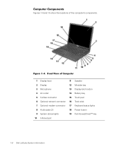
... 13 Display latch button 4 Air outlet 14 Battery bay 5 S-Video connector 15 Touch pad 6 Optional network connector 16 Track stick 7 Optional modem connector 17 Keyboard status lights 8 Audio jacks (2) 18 Power button 9 System status lights 19 Dell AccessDirect™ key 10 Infrared port 1-8 Dell Latitude System Information Front View of the computer's components. Figure 1-4.
... 13 Display latch button 4 Air outlet 14 Battery bay 5 S-Video connector 15 Touch pad 6 Optional network connector 16 Track stick 7 Optional modem connector 17 Keyboard status lights 8 Audio jacks (2) 18 Power button 9 System status lights 19 Dell AccessDirect™ key 10 Infrared port 1-8 Dell Latitude System Information Front View of the computer's components. Figure 1-4.


