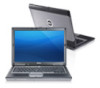
Owners Manual
Page 2
... Installing the System Fan...15 Removing the Keyboard...15 Installing the Keyboard...17 Removing the Palmrest Assembly...17 Installing the Palmrest Assembly...19 Removing the Power-Switch Board...20 Installing the Power-Switch Board...20 Removing the Fingerprint-Scanner Board...20 Installing the Fingerprint-Scanner Board...21
... Installing the System Fan...15 Removing the Keyboard...15 Installing the Keyboard...17 Removing the Palmrest Assembly...17 Installing the Palmrest Assembly...19 Removing the Power-Switch Board...20 Installing the Power-Switch Board...20 Removing the Fingerprint-Scanner Board...20 Installing the Fingerprint-Scanner Board...21
Owners Manual
Page 3
...Bezel...21 Installing the Display Bezel...22 Removing the Display Panel...22 Installing the Display Panel...23 Removing the Power LED Board...24 Installing the Power LED Board...24 Removing the Camera...24 Installing the Camera...25 Removing the Speakers...25 Installing the Speakers...26...Sniffer Board...30 Installing the Sniffer Board...31 Removing the Display Assembly...31 Installing the Display Assembly...33 Removing the Power Connector...33 Installing the Power Connector...34 Removing the System Board...34 Installing the System Board...36 Removing the Thermal Module...36 Installing the ...
...Bezel...21 Installing the Display Bezel...22 Removing the Display Panel...22 Installing the Display Panel...23 Removing the Power LED Board...24 Installing the Power LED Board...24 Removing the Camera...24 Installing the Camera...25 Removing the Speakers...25 Installing the Speakers...26...Sniffer Board...30 Installing the Sniffer Board...31 Removing the Display Assembly...31 Installing the Display Assembly...33 Removing the Power Connector...33 Installing the Power Connector...34 Removing the System Board...34 Installing the System Board...36 Removing the Thermal Module...36 Installing the ...
Owners Manual
Page 5
... computer cover from being scratched. 2. CAUTION: Before touching anything inside the computer. 1. Hold a component such as the metal at www.dell.com/ regulatory_compliance CAUTION: Many repairs may appear differently than shown in reverse order. CAUTION: When you disconnect a cable, pull on its ...Disconnect all attached devices from potential damage and to help protect your computer from their electrical outlets. 5. Press and hold the power button while the computer is unplugged to avoid bending any connector pins. As you are correctly oriented and aligned. Read and ...
... computer cover from being scratched. 2. CAUTION: Before touching anything inside the computer. 1. Hold a component such as the metal at www.dell.com/ regulatory_compliance CAUTION: Many repairs may appear differently than shown in reverse order. CAUTION: When you disconnect a cable, pull on its ...Disconnect all attached devices from potential damage and to help protect your computer from their electrical outlets. 5. Press and hold the power button while the computer is unplugged to avoid bending any connector pins. As you are correctly oriented and aligned. Read and ...
Owners Manual
Page 6
...-right corner of the Start menu as shown below, and then click Shut Down. 2. Ensure that the computer works correctly by running the Dell Diagnostics. 6 Connect your computer and all attached devices are turned off your computer. 3. Shut down . Click on your operating system, press and... hold the power button for about 6 seconds to your computer. 1. Turn on the - In Windows 8: If you shut down - In Windows Vista: Click Start , then...
...-right corner of the Start menu as shown below, and then click Shut Down. 2. Ensure that the computer works correctly by running the Dell Diagnostics. 6 Connect your computer and all attached devices are turned off your computer. 3. Shut down . Click on your operating system, press and... hold the power button for about 6 seconds to your computer. 1. Turn on the - In Windows 8: If you shut down - In Windows Vista: Click Start , then...

Owners Manual
Page 18
3. Remove the screws that secure the palmrest assembly to the computer. 18 Disconnect the media-board cable, power-switch cable, touchpad cable, fingerprint-scanner cable and speaker cable. 4.
3. Remove the screws that secure the palmrest assembly to the computer. 18 Disconnect the media-board cable, power-switch cable, touchpad cable, fingerprint-scanner cable and speaker cable. 4.

Owners Manual
Page 19
... the screws that secure the palmrest assembly to the computer. 4. Installing the Palmrest Assembly 1. Connect the following cable: a) Speaker cable b) fingerprint-scanner cable c) touchpad cable d) power-switch cable 19 Tighten the screws to secure the palmrest assembly to the base of the computer and flip open the lower assembly. 6. Tighten the...
... the screws that secure the palmrest assembly to the computer. 4. Installing the Palmrest Assembly 1. Connect the following cable: a) Speaker cable b) fingerprint-scanner cable c) touchpad cable d) power-switch cable 19 Tighten the screws to secure the palmrest assembly to the base of the computer and flip open the lower assembly. 6. Tighten the...
Owners Manual
Page 20
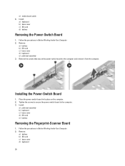
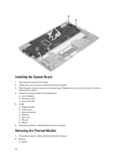
...3. Follow the procedures in its place on the computer. 2. Remove: a) battery b) SD card c) base cover d) keyboard 20 Installing the Power-Switch Board 1. Place the power-switch board in Before Working Inside Your Computer. 2. Install: a) palmrest assembly b) keyboard c) base cover d) SD card e) battery Removing the ... Computer. 2. Remove: a) battery b) SD card c) base cover d) keyboard e) palmrest assembly 3. Tighten the screws to secure the power-switch board to the computer and remove it from the computer. Install: a) keyboard b) base cover c) SD card d) battery Removing the...
...3. Follow the procedures in its place on the computer. 2. Remove: a) battery b) SD card c) base cover d) keyboard 20 Installing the Power-Switch Board 1. Place the power-switch board in Before Working Inside Your Computer. 2. Install: a) palmrest assembly b) keyboard c) base cover d) SD card e) battery Removing the ... Computer. 2. Remove: a) battery b) SD card c) base cover d) keyboard e) palmrest assembly 3. Tighten the screws to secure the power-switch board to the computer and remove it from the computer. Install: a) keyboard b) base cover c) SD card d) battery Removing the...

Owners Manual
Page 24
... the computer. 4. Follow the procedures in Before Working Inside Your Computer. 2. Remove: a) battery b) display bezel 3. Remove the screw that secure the power LED board to the computer and flip the power LED board over. 4. Disconnect the LVDS and camera cable. 4. Follow the procedures in After Working Inside Your Computer. Remove the screws...
... the computer. 4. Follow the procedures in Before Working Inside Your Computer. 2. Remove: a) battery b) display bezel 3. Remove the screw that secure the power LED board to the computer and flip the power LED board over. 4. Disconnect the LVDS and camera cable. 4. Follow the procedures in After Working Inside Your Computer. Remove the screws...
Owners Manual
Page 33
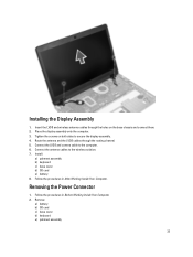
... cables to the computer. 6. Install: a) palmrest assembly b) keyboard c) base cover d) SD card e) battery 8. Connect the LVDS and camera cable to the wireless solution. 7. Removing the Power Connector 1. Remove: a) battery b) SD card c) base cover d) keyboard e) palmrest assembly 33 Place the display assembly onto the computer. 3. Follow the procedures in After Working Inside...
... cables to the computer. 6. Install: a) palmrest assembly b) keyboard c) base cover d) SD card e) battery 8. Connect the LVDS and camera cable to the wireless solution. 7. Removing the Power Connector 1. Remove: a) battery b) SD card c) base cover d) keyboard e) palmrest assembly 33 Place the display assembly onto the computer. 3. Follow the procedures in After Working Inside...
Owners Manual
Page 34
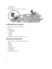
...Follow the procedures in After Working Inside Your Computer. Installing the Power Connector 1. Remove: a) battery b) SD card c) base cover d) keyboard e) palmrest assembly f) sniffer board g) display assembly 3. Connect the power-connector cable to the computer. 2. Disconnect the system-fan cable.... 34 f) display assembly g) system board 3. Disconnect the power-connector cable from the computer. Removing the System Board 1. Follow ...
...Follow the procedures in After Working Inside Your Computer. Installing the Power Connector 1. Remove: a) battery b) SD card c) base cover d) keyboard e) palmrest assembly f) sniffer board g) display assembly 3. Connect the power-connector cable to the computer. 2. Disconnect the system-fan cable.... 34 f) display assembly g) system board 3. Disconnect the power-connector cable from the computer. Removing the System Board 1. Follow ...

Owners Manual
Page 35
Remove the screws that secure the system board to the computer and remove the power-connector bracket from the computer. 6. Remove the screws that secure the power-connector bracket to the computer and remove it. 35 4. Disconnect the smart-card cable, hall-sensor cable and coin-cell battery cable. 5.
Remove the screws that secure the system board to the computer and remove the power-connector bracket from the computer. 6. Remove the screws that secure the power-connector bracket to the computer and remove it. 35 4. Disconnect the smart-card cable, hall-sensor cable and coin-cell battery cable. 5.
Owners Manual
Page 36
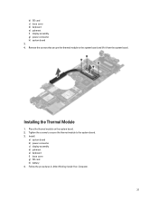
Installing the System Board 1. Place the power-connector bracket on the chassis. 2. Install: a) display assembly b) sniffer board c) palmrest assembly d) keyboard e) base cover f) SD card g) battery 6. Removing the Thermal Module 1. Tighten the screws... to secure the system board to the computer. 4. Follow the procedures in Before Working Inside Your Computer. 2. Tighten the screws to secure the power-connector bracket to the computer. 3. Connect the following cables to the system board: a) coin-cell battery b) hall-sensor cable c) smart-card cable 5. Follow the ...
Installing the System Board 1. Place the power-connector bracket on the chassis. 2. Install: a) display assembly b) sniffer board c) palmrest assembly d) keyboard e) base cover f) SD card g) battery 6. Removing the Thermal Module 1. Tighten the screws... to secure the system board to the computer. 4. Follow the procedures in Before Working Inside Your Computer. 2. Tighten the screws to secure the power-connector bracket to the computer. 3. Connect the following cables to the system board: a) coin-cell battery b) hall-sensor cable c) smart-card cable 5. Follow the ...
Owners Manual
Page 37
Install: a) system board b) power connector c) display assembly d) palmrest e) keyboard f) base cover g) SD card h) battery 4. Remove the screws that secure the thermal module to the system board. 3. Place the thermal module on the system board. 2. Tighten the screws to secure the thermal module to the system board and lift it from the system board. Follow the procedures in After Working Inside Your Computer. 37 b) SD card c) base cover d) keyboard e) palmrest f) display assembly g) power connector h) system board 3. 4. Installing the Thermal Module 1.
Install: a) system board b) power connector c) display assembly d) palmrest e) keyboard f) base cover g) SD card h) battery 4. Remove the screws that secure the thermal module to the system board. 3. Place the thermal module on the system board. 2. Tighten the screws to secure the thermal module to the system board and lift it from the system board. Follow the procedures in After Working Inside Your Computer. 37 b) SD card c) base cover d) keyboard e) palmrest f) display assembly g) power connector h) system board 3. 4. Installing the Thermal Module 1.
Owners Manual
Page 39
Certain changes can boot from including the diagnostic option. The boot sequence screen also displays the option to work incorrectly. During the Power-on Self Test (POST), when the Dell logo appears, you can: • Access System Setup by pressing key • Bring up the one-time boot menu by pressing key The...
Certain changes can boot from including the diagnostic option. The boot sequence screen also displays the option to work incorrectly. During the Power-on Self Test (POST), when the Dell logo appears, you can: • Access System Setup by pressing key • Bring up the one-time boot menu by pressing key The...
Owners Manual
Page 40
...My Products and Services List c) Choose from a list of your BIOS (system setup), on the bottom of all Dell products 5. On the application and drivers screen, under the Operating System drop-down list, if applicable. Identify the...The File Download window appears. 8. System Setup Option General 40 Navigation Keys Keys Navigation Up arrow Moves to support.dell.com/support/downloads. 3. Down arrow Moves to the next focus area. Moves to the next field. NOTE: ...is available at the back of your computer. 9. Click Save to a power outlet 1. Click Run to step 5. 4.
...My Products and Services List c) Choose from a list of your BIOS (system setup), on the bottom of all Dell products 5. On the application and drivers screen, under the Operating System drop-down list, if applicable. Identify the...The File Download window appears. 8. System Setup Option General 40 Navigation Keys Keys Navigation Up arrow Moves to support.dell.com/support/downloads. 3. Down arrow Moves to the next focus area. Moves to the next field. NOTE: ...is available at the back of your computer. 9. Click Save to a power outlet 1. Click Run to step 5. 4.
Owners Manual
Page 42
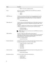
... eSATA Ports This feature is intended to allow users to charge external devices, such as phones and portable music players, using the stored system battery power through the USB PowerShare port, even when the system is enabled by default. • Enable Unobtrusive Mode Allows you to 100% • Disabled: This option...
... eSATA Ports This feature is intended to allow users to charge external devices, such as phones and portable music players, using the stored system battery power through the USB PowerShare port, even when the system is enabled by default. • Enable Unobtrusive Mode Allows you to 100% • Disabled: This option...

Owners Manual
Page 43
... by default. Security Table 5. Default Setting: Enable Strong Password is installed into the system. Allows you to set the display brightness depending up on the power source (On Battery and On AC). Default Setting: Not set Allows you to enable or disable the permission to set or change or delete the...
... by default. Security Table 5. Default Setting: Enable Strong Password is installed into the system. Allows you to set the display brightness depending up on the power source (On Battery and On AC). Default Setting: Not set Allows you to enable or disable the permission to set or change or delete the...
Owners Manual
Page 45
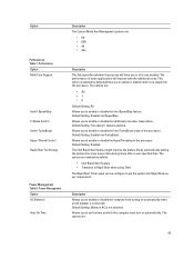
Performance Option Multi Core Support Intel® SpeedStep C States Control Intel® TurboBoost Hyper-Thread Control Rapid Start Technology Power Management Table 8. Default Setting: Enable Intel TurboBoost Allows you to enable or disable the HyperThreading in the processor. Default ...is connected. The options are enabled by default.Allows you to put the system into a low power state during sleep after a user specified time. This option is not selected. Power Management Option AC Behavior Auto On Time Description The Custom Mode Key Management options are : 45 ...
Performance Option Multi Core Support Intel® SpeedStep C States Control Intel® TurboBoost Hyper-Thread Control Rapid Start Technology Power Management Table 8. Default Setting: Enable Intel TurboBoost Allows you to enable or disable the HyperThreading in the processor. Default ...is connected. The options are enabled by default.Allows you to put the system into a low power state during sleep after a user specified time. This option is not selected. Power Management Option AC Behavior Auto On Time Description The Custom Mode Key Management options are : 45 ...
Owners Manual
Page 46
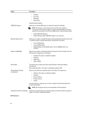
.... Block Sleep (S3 state) - The option is not selected Wake on LAN/WLAN Allows you to enable or disable the feature that powers on the physical connection. • Control WLAN Radio • Control WWAN Radio • Default Setting: Control WLAN radio or Control WWAN...Connect Technology Allows you to periodically sense nearby wireless connections while the system is connected. NOTE: This feature is only functional when the AC power adapter is asleep. Option Description USB Wake Support • Disabled • Every Day • Weekdays • Select Days Default Setting...
.... Block Sleep (S3 state) - The option is not selected Wake on LAN/WLAN Allows you to enable or disable the feature that powers on the physical connection. • Control WLAN Radio • Control WWAN Radio • Default Setting: Control WLAN radio or Control WWAN...Connect Technology Allows you to periodically sense nearby wireless connections while the system is connected. NOTE: This feature is only functional when the AC power adapter is asleep. Option Description USB Wake Support • Disabled • Every Day • Weekdays • Select Days Default Setting...
Owners Manual
Page 47
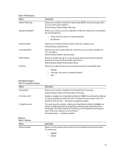
... I /O Trusted Execution Wireless Table 11. Default Setting: Enable Network Allows you enable the sign-on screen message display indicating the keystroke sequence to use certain power adapters. The TPM virtualization Technology, and Virtualization technology for Direct I /O must be controlled by default. • By Numlock Allows you to enable or disable the...
... I /O Trusted Execution Wireless Table 11. Default Setting: Enable Network Allows you enable the sign-on screen message display indicating the keystroke sequence to use certain power adapters. The TPM virtualization Technology, and Virtualization technology for Direct I /O must be controlled by default. • By Numlock Allows you to enable or disable the...


