
Inspiron 20 3059 Specifications
Page 5
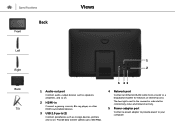
... port Connect audio-output devices such as speakers, amplifiers, and so on. 2 HDMI-in Connect a gaming console, Blu‑ray player, or other HDMI‑out enabled devices. 3 USB 2.0 ports (2) Connect peripherals such as storage devices, printers, and so on. Provide data transfer speeds up to your computer. The two lights next to the connector indicate the connectivity status and network activity. 5 Power-adapter port Connect a power adapter to provide power to 480 Mbps. 4 Network port Connect an Ethernet (RJ45) cable...
... port Connect audio-output devices such as speakers, amplifiers, and so on. 2 HDMI-in Connect a gaming console, Blu‑ray player, or other HDMI‑out enabled devices. 3 USB 2.0 ports (2) Connect peripherals such as storage devices, printers, and so on. Provide data transfer speeds up to your computer. The two lights next to the connector indicate the connectivity status and network activity. 5 Power-adapter port Connect a power adapter to provide power to 480 Mbps. 4 Network port Connect an Ethernet (RJ45) cable...
Inspiron 20 3059 Specifications
Page 8
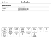
Views System information Computer model Processor Chipset v Specifications Inspiron 20-3059 • 6th generation Intel Core i3 • 6th generation Intel Core i5 Integrated in processor Dimensions and weight System information Memory Ports and connectors Communications Video Audio Media-card reader Display Camera Stand Power adapter Computer environment Storage
Views System information Computer model Processor Chipset v Specifications Inspiron 20-3059 • 6th generation Intel Core i3 • 6th generation Intel Core i5 Integrated in processor Dimensions and weight System information Memory Ports and connectors Communications Video Audio Media-card reader Display Camera Stand Power adapter Computer environment Storage

Inspiron 20 3059 Specifications
Page 10
Views Ports and connectors External: Network USB Audio/Video Internal: M.2 Specifications One RJ45 port • Two USB 2.0 ports • Two USB 3.0 ports • One headset port • One audio line-out port • One HDMI-in port One M.2 slot for WLAN and Bluetooth combo card Dimensions and weight System information Memory Ports and connectors Communications Video Audio Media-card reader Display Camera Stand Power adapter Computer environment Storage
Views Ports and connectors External: Network USB Audio/Video Internal: M.2 Specifications One RJ45 port • Two USB 2.0 ports • Two USB 3.0 ports • One headset port • One audio line-out port • One HDMI-in port One M.2 slot for WLAN and Bluetooth combo card Dimensions and weight System information Memory Ports and connectors Communications Video Audio Media-card reader Display Camera Stand Power adapter Computer environment Storage
Inspiron 20 3059 Specifications
Page 11
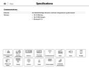
Views Communications Ethernet Wireless Specifications 10/100/1000 Mbps Ethernet controller integrated on system board • Wi-Fi 802.11ac • Wi-Fi 802.11b/g/n • Bluetooth 4.0 Dimensions and weight System information Memory Ports and connectors Communications Video Audio Media-card reader Display Camera Stand Power adapter Computer environment Storage
Views Communications Ethernet Wireless Specifications 10/100/1000 Mbps Ethernet controller integrated on system board • Wi-Fi 802.11ac • Wi-Fi 802.11b/g/n • Bluetooth 4.0 Dimensions and weight System information Memory Ports and connectors Communications Video Audio Media-card reader Display Camera Stand Power adapter Computer environment Storage

Inspiron 20 3059 Specifications
Page 14
Views Storage Interface Hard drive Optical drive Specifications • SATA 3 Gbps for optical drive • SATA 6 Gbps for hard drive One 2.5-inch drive One 9.5-mm DVD+/-RW drive (optional) Dimensions and weight System information Memory Ports and connectors Communications Video Audio Media-card reader Display Camera Stand Power adapter Computer environment Storage
Views Storage Interface Hard drive Optical drive Specifications • SATA 3 Gbps for optical drive • SATA 6 Gbps for hard drive One 2.5-inch drive One 9.5-mm DVD+/-RW drive (optional) Dimensions and weight System information Memory Ports and connectors Communications Video Audio Media-card reader Display Camera Stand Power adapter Computer environment Storage

Inspiron 20 3059 Specifications
Page 16
Views Display Type Resolution (maximum) Dimensions: Height Width Diagonal Refresh rate Pixel pitch Controls Specifications • 19.5-inch HD+ touch screen • 19.5-inch HD+ non-touch screen 1600 x 900 263 mm (10.35 in) 452 mm (17.80 in) 495.30 mm (19.50 in) 60 Hz 0.2745 mm x 0.2745 mm Brightness can be controlled through the display-brightness control buttons Dimensions and weight System information Memory Ports and connectors Communications Video Audio Media-card reader Display Camera Stand Power adapter Computer environment Storage
Views Display Type Resolution (maximum) Dimensions: Height Width Diagonal Refresh rate Pixel pitch Controls Specifications • 19.5-inch HD+ touch screen • 19.5-inch HD+ non-touch screen 1600 x 900 263 mm (10.35 in) 452 mm (17.80 in) 495.30 mm (19.50 in) 60 Hz 0.2745 mm x 0.2745 mm Brightness can be controlled through the display-brightness control buttons Dimensions and weight System information Memory Ports and connectors Communications Video Audio Media-card reader Display Camera Stand Power adapter Computer environment Storage

Inspiron 20 3059 Specifications
Page 20
... weight System information Memory Ports and connectors Communications Video Audio Media-card reader Display Camera Stand Power adapter Computer environment Storage Storage -40°C to 65°C (-40°F to 149°F) 0% to 95% (non-condensing) 1.30 GRMS 160 G‡ -15.2 m to 10,668 m (-50 ft to 10,000 ft) * Measured using a random vibration spectrum that simulates user environment. † Measured using a 2 ms half...
... weight System information Memory Ports and connectors Communications Video Audio Media-card reader Display Camera Stand Power adapter Computer environment Storage Storage -40°C to 65°C (-40°F to 149°F) 0% to 95% (non-condensing) 1.30 GRMS 160 G‡ -15.2 m to 10,668 m (-50 ft to 10,000 ft) * Measured using a random vibration spectrum that simulates user environment. † Measured using a 2 ms half...
Inspiron 20 3059 Service Manual
Page 4
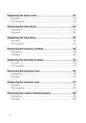
Replacing the back cover 25 Procedure...25 Post-requisites 25 Removing the hard drive 26 Prerequisites...26 Procedure...26 Replacing the hard drive 29 Procedure...29 Post-requisites 29 Removing the memory module 30 Prerequisites...30 Procedure...30 Replacing the memory module 32 Procedure...32 Post-requisites 33 Removing the wireless card 35 Prerequisites...35 Procedure...35 Replacing the wireless card 37 Procedure...37 Post-requisites 39 Removing the control-buttons board 40 Prerequisites...40 Procedure...40 4
Replacing the back cover 25 Procedure...25 Post-requisites 25 Removing the hard drive 26 Prerequisites...26 Procedure...26 Replacing the hard drive 29 Procedure...29 Post-requisites 29 Removing the memory module 30 Prerequisites...30 Procedure...30 Replacing the memory module 32 Procedure...32 Post-requisites 33 Removing the wireless card 35 Prerequisites...35 Procedure...35 Replacing the wireless card 37 Procedure...37 Post-requisites 39 Removing the control-buttons board 40 Prerequisites...40 Procedure...40 4
Inspiron 20 3059 Service Manual
Page 9
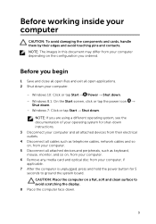
... cables such as keyboard, mouse, monitor, and so on the configuration you begin 1 Save and close all open files and exit all attached devices and peripherals, such as telephone cables, network cables and so on, from your computer CAUTION: To avoid damaging the components and cards, handle them by their edges and avoid touching pins and contacts. NOTE: If you are using a different operating...
... cables such as keyboard, mouse, monitor, and so on the configuration you begin 1 Save and close all open files and exit all attached devices and peripherals, such as telephone cables, network cables and so on, from your computer CAUTION: To avoid damaging the components and cards, handle them by their edges and avoid touching pins and contacts. NOTE: If you are using a different operating...
Inspiron 20 3059 Service Manual
Page 10
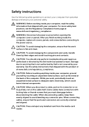
... touching anything inside the computer, replace all power sources before connecting to dissipate static electricity, which could harm internal components. CAUTION: You should only perform troubleshooting and repairs as the metal at the back of the computer. CAUTION: Press and eject any connector pins. See the safety instructions that shipped with locking tabs or thumb-screws that the ports and connectors are...
... touching anything inside the computer, replace all power sources before connecting to dissipate static electricity, which could harm internal components. CAUTION: You should only perform troubleshooting and repairs as the metal at the back of the computer. CAUTION: Press and eject any connector pins. See the safety instructions that shipped with locking tabs or thumb-screws that the ports and connectors are...

Inspiron 20 3059 Service Manual
Page 12
After working inside your computer CAUTION: Leaving stray or loose screws inside your computer may severely damage your computer. 1 Replace all screws and ensure that no stray screws remain inside your computer. 2 Connect any external devices, peripherals, and cables you removed before working on your computer. 3 Replace any media cards, discs, and any other parts that you removed before working on your computer. 4 Connect your computer and all attached devices to their electrical outlets. 5 Turn on your computer. 12
After working inside your computer CAUTION: Leaving stray or loose screws inside your computer may severely damage your computer. 1 Replace all screws and ensure that no stray screws remain inside your computer. 2 Connect any external devices, peripherals, and cables you removed before working on your computer. 3 Replace any media cards, discs, and any other parts that you removed before working on your computer. 4 Connect your computer and all attached devices to their electrical outlets. 5 Turn on your computer. 12

Inspiron 20 3059 Service Manual
Page 26
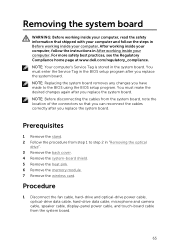
... best practices, see the Regulatory Compliance home page at www.dell.com/regulatory_compliance. After working inside your computer. Procedure 1 Note the routing of the touch-screen board cable and remove it from the hard drive. 3 Remove the screw that shipped with your computer and follow the instructions in After working inside your computer, follow the steps in "Removing the optical drive". 3 Remove the back cover. CAUTION: Hard drives are fragile.
... best practices, see the Regulatory Compliance home page at www.dell.com/regulatory_compliance. After working inside your computer. Procedure 1 Note the routing of the touch-screen board cable and remove it from the hard drive. 3 Remove the screw that shipped with your computer and follow the instructions in After working inside your computer, follow the steps in "Removing the optical drive". 3 Remove the back cover. CAUTION: Hard drives are fragile.

Inspiron 20 3059 Service Manual
Page 27
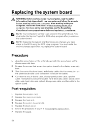
4 Slide and lift the hard-drive assembly off the display-assembly base. 1 touch-screen board cable 3 hard-drive cable 2 screw 4 hard-drive assembly 5 Remove the screws that secure the hard-drive bracket to the hard drive. 27
4 Slide and lift the hard-drive assembly off the display-assembly base. 1 touch-screen board cable 3 hard-drive cable 2 screw 4 hard-drive assembly 5 Remove the screws that secure the hard-drive bracket to the hard drive. 27

Inspiron 20 3059 Service Manual
Page 29
... shipped with your computer and follow the instructions in After working inside your computer. CAUTION: Hard drives are fragile. assembly base. 6 Connect the power and data cable to the hard drive. 7 Route the touch-board cable through the routing guides on the harddrive bracket . 2 Replace the screws that secures the hard-drive assembly to the hard drive. 3 Align the tabs on the hard-drive assembly with the screw holes on the...
... shipped with your computer and follow the instructions in After working inside your computer. CAUTION: Hard drives are fragile. assembly base. 6 Connect the power and data cable to the hard drive. 7 Route the touch-board cable through the routing guides on the harddrive bracket . 2 Replace the screws that secures the hard-drive assembly to the hard drive. 3 Align the tabs on the hard-drive assembly with the screw holes on the...

Inspiron 20 3059 Service Manual
Page 33
2 Slide the memory module firmly into the slot at an angle and press the memory module down until it . 1 memory module 3 notch Post-requisites 1 Replace the system-board shield. 2 Replace the back cover. 2 memory-module slot 4 tab 33 NOTE: If you do not hear the click, remove the memory module and reinstall it clicks into place.
2 Slide the memory module firmly into the slot at an angle and press the memory module down until it . 1 memory module 3 notch Post-requisites 1 Replace the system-board shield. 2 Replace the back cover. 2 memory-module slot 4 tab 33 NOTE: If you do not hear the click, remove the memory module and reinstall it clicks into place.

Inspiron 20 3059 Service Manual
Page 64
Post-requisites 1 Replace the system-board shield. 2 Replace the back cover. 3 Follow the procedure in step 4 in "Replacing the optical drive". 4 Replace the stand. 64 Procedure 1 Using the alignment posts and rubber grommets on the display bezel, place the speakers on the display bezel. 2 Route the speaker cable through the routing guides on the display bezel and the display-panel base. 3 Connect the speaker cable to the system board. After working inside your computer, follow...
Post-requisites 1 Replace the system-board shield. 2 Replace the back cover. 3 Follow the procedure in step 4 in "Replacing the optical drive". 4 Replace the stand. 64 Procedure 1 Using the alignment posts and rubber grommets on the display bezel, place the speakers on the display bezel. 2 Route the speaker cable through the routing guides on the display bezel and the display-panel base. 3 Connect the speaker cable to the system board. After working inside your computer, follow...
Inspiron 20 3059 Service Manual
Page 65
... from step 1 to the BIOS using the BIOS setup program. After working inside your computer, follow the steps in Before working inside your computer. Procedure 1 Disconnect the fan cable, hard-drive and optical-drive power cable, optical-drive data cable, hard-drive data cable, microphone and camera cable, speaker cable, display-panel power cable, and touch-board cable from the system board, note the location of the connectors so that shipped with your computer and follow the instructions in the system board. NOTE: Before disconnecting the...
... from step 1 to the BIOS using the BIOS setup program. After working inside your computer, follow the steps in Before working inside your computer. Procedure 1 Disconnect the fan cable, hard-drive and optical-drive power cable, optical-drive data cable, hard-drive data cable, microphone and camera cable, speaker cable, display-panel power cable, and touch-board cable from the system board, note the location of the connectors so that shipped with your computer and follow the instructions in the system board. NOTE: Before disconnecting the...
Inspiron 20 3059 Service Manual
Page 68
... the cables. 4 Connect the touch-board cable, display-panel power cable, speaker cable, microphone and camera cable, hard-drive data cable, optical-drive data cable, hard-drive and optical-drive power cable, and fan cable to the BIOS using the BIOS setup program. For more safety best practices, see the Regulatory Compliance home page at www.dell.com/regulatory_compliance. You must make the desired changes again after you replace the system board. You must enter the Service Tag in the BIOS setup program after you replace the system board. NOTE: Replacing...
... the cables. 4 Connect the touch-board cable, display-panel power cable, speaker cable, microphone and camera cable, hard-drive data cable, optical-drive data cable, hard-drive and optical-drive power cable, and fan cable to the BIOS using the BIOS setup program. For more safety best practices, see the Regulatory Compliance home page at www.dell.com/regulatory_compliance. You must make the desired changes again after you replace the system board. You must enter the Service Tag in the BIOS setup program after you replace the system board. NOTE: Replacing...
Inspiron 20 3059 Service Manual
Page 81
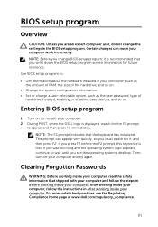
... the instructions in your computer, such as the amount of RAM, the size of the hard drive, and so on. • Change the system configuration information. • Set or change a user-selectable option, such as the user password, type of hard drive installed, enabling or disabling base devices, and so on (or restart) your computer. 2 During POST, when the DELL logo is displayed, watch for it is lost. Entering BIOS setup program 1 Turn on . After working inside...
... the instructions in your computer, such as the amount of RAM, the size of the hard drive, and so on. • Change the system configuration information. • Set or change a user-selectable option, such as the user password, type of hard drive installed, enabling or disabling base devices, and so on (or restart) your computer. 2 During POST, when the DELL logo is displayed, watch for it is lost. Entering BIOS setup program 1 Turn on . After working inside...
Inspiron 20 3059 Service Manual
Page 84
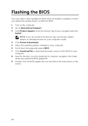
... saved the BIOS update file. 9 Double-click the BIOS update file icon and follow the instructions on your computer. 6 Scroll down the page and expand BIOS. 7 Click Download File to download the latest version of your computer model. 4 Click Drivers & downloads. 5 Select the operating system installed on the screen. 84 To flash the BIOS: 1 Turn on the computer. 2 Go to www.dell.com/support. 3 Click Product Support, enter the Service Tag of...
... saved the BIOS update file. 9 Double-click the BIOS update file icon and follow the instructions on your computer. 6 Scroll down the page and expand BIOS. 7 Click Download File to download the latest version of your computer model. 4 Click Drivers & downloads. 5 Select the operating system installed on the screen. 84 To flash the BIOS: 1 Turn on the computer. 2 Go to www.dell.com/support. 3 Click Product Support, enter the Service Tag of...


