Service Manual
Page 1
...any manner whatsoever without notice. © 2003-2005 Dell Inc. Dell™ Inspiron™ 300m Service Manual Before You Begin Dell Diagnostics System Components Battery Memory, Modem, and Mini PCI Card Modules Keyboard Palm Rest Hard Drive Hinge Covers and Display Assembly Keyboard Tray Reserve Battery Speakers... the problem. Information in this document is strictly forbidden. under license. May 2005 Rev. Intel is a trademark owned by Dell Inc. Bluetooth is a registered trademark of Intel Corporation; Other trademarks and trade names may be used in any proprietary interest ...
...any manner whatsoever without notice. © 2003-2005 Dell Inc. Dell™ Inspiron™ 300m Service Manual Before You Begin Dell Diagnostics System Components Battery Memory, Modem, and Mini PCI Card Modules Keyboard Palm Rest Hard Drive Hinge Covers and Display Assembly Keyboard Tray Reserve Battery Speakers... the problem. Information in this document is strictly forbidden. under license. May 2005 Rev. Intel is a trademark owned by Dell Inc. Bluetooth is a registered trademark of Intel Corporation; Other trademarks and trade names may be used in any proprietary interest ...
Service Manual
Page 2
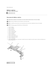
.... 9. NOTICE: Disconnect the computer and any of the bottom case, use your fingers to Contents Page Battery Latches Dell™ Inspiron™ 300m Service Manual Removing the Battery Latches Replacing the Battery Latches Removing the Battery Latches CAUTION: Before you begin any attached devices... from the bottom case and the snap tabs, catching the latch button on the computer. Remove the keyboard. 3. Remove the hinge ...
.... 9. NOTICE: Disconnect the computer and any of the bottom case, use your fingers to Contents Page Battery Latches Dell™ Inspiron™ 300m Service Manual Removing the Battery Latches Replacing the Battery Latches Removing the Battery Latches CAUTION: Before you begin any attached devices... from the bottom case and the snap tabs, catching the latch button on the computer. Remove the keyboard. 3. Remove the hinge ...
Service Manual
Page 14
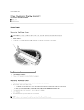
...in this section, follow the safety instructions in their respective slots. 3. The left hinge cover fits over the display hinges: a. Remove the battery. 2. Press down on the hinge covers to remove them from the back of the computer. Ensure that it lies ...use your work surface. 2. Both hinge covers pass through the display hinges to the back of the computer. 1 hinge covers (2) 3. Back to Contents Page Hinge Covers and Display Assembly Dell™ Inspiron™ 300m Service Manual Hinge Covers Display Assembly Hinge Covers Removing the Hinge Covers CAUTION: Before you begin ...
...in this section, follow the safety instructions in their respective slots. 3. The left hinge cover fits over the display hinges: a. Remove the battery. 2. Press down on the hinge covers to remove them from the back of the computer. Ensure that it lies ...use your work surface. 2. Both hinge covers pass through the display hinges to the back of the computer. 1 hinge covers (2) 3. Back to Contents Page Hinge Covers and Display Assembly Dell™ Inspiron™ 300m Service Manual Hinge Covers Display Assembly Hinge Covers Removing the Hinge Covers CAUTION: Before you begin ...

Service Manual
Page 16
... on the top of the computer. 8. Remove the display assembly out of the computer. 3. Replace the two M2 x 6-mm screws by the display hinges on the top of the bottom case. Close the display and turn the computer over. 7. If a tape secures the signal connector, remove it and... 8. Pull the signal connector to Contents Page Connect the signal cable to the system board. 6. Remove the two M2 x 6-mm screws near the display hinges on the signal cable. Replace the display assembly into the bottom case and open the display 180 degrees. 2. Replace the battery. Replace the keyboard. 9. ...
... on the top of the computer. 8. Remove the display assembly out of the computer. 3. Replace the two M2 x 6-mm screws by the display hinges on the top of the bottom case. Close the display and turn the computer over. 7. If a tape secures the signal connector, remove it and... 8. Pull the signal connector to Contents Page Connect the signal cable to the system board. 6. Remove the two M2 x 6-mm screws near the display hinges on the signal cable. Replace the display assembly into the bottom case and open the display 180 degrees. 2. Replace the battery. Replace the keyboard. 9. ...
Service Manual
Page 24
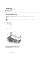
... the Keyboard Tray Remove the five M2 x 4-mm screws that secure the keyboard tray to Contents Page Keyboard Tray Dell™ Inspiron™ 300m Service Manual Removing the Keyboard Tray Replacing the Keyboard Tray Removing the Keyboard Tray CAUTION: Before you begin any attached devices...: Each keyboard tray screw has an arrow beside it. 1 keyboard tray 2 M2 x 4-mm screws (5) 7. Remove the palm rest. 4. Remove the hinge covers. 5. Remove the display assembly. 6. NOTICE: Read "Before You Begin" before lifting the tray out of the procedures in this section, follow the safety...
... the Keyboard Tray Remove the five M2 x 4-mm screws that secure the keyboard tray to Contents Page Keyboard Tray Dell™ Inspiron™ 300m Service Manual Removing the Keyboard Tray Replacing the Keyboard Tray Removing the Keyboard Tray CAUTION: Before you begin any attached devices...: Each keyboard tray screw has an arrow beside it. 1 keyboard tray 2 M2 x 4-mm screws (5) 7. Remove the palm rest. 4. Remove the hinge covers. 5. Remove the display assembly. 6. NOTICE: Read "Before You Begin" before lifting the tray out of the procedures in this section, follow the safety...

Service Manual
Page 27
... 2U381 9Y200 H0294 J0846 N0498 Screws 2013T 6K709 6R788 7T775 8T707 98MKC Speaker 7C552 Palm Rest Assembly G0808 Back to Contents Page left hinge cover right hinge cover 12.1 LCD hinge up assembly 128-MB DIMM 256-MB DIMM 512-MB DIMM 1-G DIMM 56-K V2 internal modem system-board service kit, 1.2 GHz, (non...
... 2U381 9Y200 H0294 J0846 N0498 Screws 2013T 6K709 6R788 7T775 8T707 98MKC Speaker 7C552 Palm Rest Assembly G0808 Back to Contents Page left hinge cover right hinge cover 12.1 LCD hinge up assembly 128-MB DIMM 256-MB DIMM 512-MB DIMM 1-G DIMM 56-K V2 internal modem system-board service kit, 1.2 GHz, (non...
Service Manual
Page 40
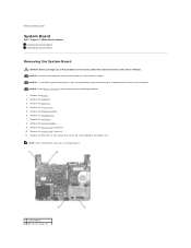
... card, if present. 10. Remove the display assembly. 6. Remove the three M2 x 4-mm screws that secure the system board to Contents Page System Board Dell™ Inspiron™ 300m Service Manual Removing the System Board Replacing the System Board Removing the System Board CAUTION: Before you begin any attached devices from electrical outlets...
... card, if present. 10. Remove the display assembly. 6. Remove the three M2 x 4-mm screws that secure the system board to Contents Page System Board Dell™ Inspiron™ 300m Service Manual Removing the System Board Replacing the System Board Removing the System Board CAUTION: Before you begin any attached devices from electrical outlets...
Service Manual
Page 42
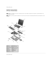
... otherwise noted, each procedure in reverse order. 1 display 8 speakers (2) 2 hinge covers (2) 9 reserve battery 3 keyboard tray 10 Bluetooth™ module 4 battery 11 system board 5 cooling fan 12 palm rest 6 hard drive 13 keyboard 7 bottom case Back to Contents Page System Components Dell™ Inspiron™ 300m Service Manual NOTICE: Only a certified service technician should perform...
... otherwise noted, each procedure in reverse order. 1 display 8 speakers (2) 2 hinge covers (2) 9 reserve battery 3 keyboard tray 10 Bluetooth™ module 4 battery 11 system board 5 cooling fan 12 palm rest 6 hard drive 13 keyboard 7 bottom case Back to Contents Page System Components Dell™ Inspiron™ 300m Service Manual NOTICE: Only a certified service technician should perform...


