
Owner's Manual
Page 10
... Drive 133 Returning a Hard Drive to Dell 134 Optical Drive 134 Removing the Optical Drive 134 Replacing the Optical Drive 135 Hinge Cover 135 Removing the Hinge Cover 136 Replacing the Hinge Cover 136 Keyboard 137 Removing the Keyboard 137 Replacing the Keyboard 138 Memory 139 Removing the Memory Module 139 Replacing the Memory Module 141 Modem 142...
... Drive 133 Returning a Hard Drive to Dell 134 Optical Drive 134 Removing the Optical Drive 134 Replacing the Optical Drive 135 Hinge Cover 135 Removing the Hinge Cover 136 Replacing the Hinge Cover 136 Keyboard 137 Removing the Keyboard 137 Replacing the Keyboard 138 Memory 139 Removing the Memory Module 139 Replacing the Memory Module 141 Modem 142...

Owner's Manual
Page 104
... the software documentation. The system configuration information does not match the hardware configuration. Run the Keyboard Controller test in the Dell Diagnostics (see "Memory" on page 139). K E Y B O A R D C O N T R O L L E R F A I O N E R R O R - K E Y B O A R D D A T A L I N E F A I L U R E - K E Y B O A R D S T U C K KEY F A I L U R E - Reinstall the memory modules and, if necessary, replace them (see "Dell Diagnostics" on page 139). Try to occur after a memory module is conflicting with the operating...
... the software documentation. The system configuration information does not match the hardware configuration. Run the Keyboard Controller test in the Dell Diagnostics (see "Memory" on page 139). K E Y B O A R D C O N T R O L L E R F A I O N E R R O R - K E Y B O A R D D A T A L I N E F A I L U R E - K E Y B O A R D S T U C K KEY F A I L U R E - Reinstall the memory modules and, if necessary, replace them (see "Dell Diagnostics" on page 139). Try to occur after a memory module is conflicting with the operating...

Owner's Manual
Page 106
...Troubleshooting OF - If the message reappears, contact Dell (see "Using the System Setup Program" on the hard drive. Connect your computer to an electrical outlet to an electrical outlet; X : \ I S N O T A C C E S S I N P R O T E C T E D M O D E - WA R N I N G : B A T T E R Y I S C R I T I C A L L Y L O W - Replace the battery, or connect the computer to ...). Correct the settings for the Date and Time options (see "Contacting Dell" on page 93). A chip on page 177). The keyboard controller may be malfunctioning, or a memory module may require recharging. SEEK ERROR -
...Troubleshooting OF - If the message reappears, contact Dell (see "Using the System Setup Program" on the hard drive. Connect your computer to an electrical outlet to an electrical outlet; X : \ I S N O T A C C E S S I N P R O T E C T E D M O D E - WA R N I N G : B A T T E R Y I S C R I T I C A L L Y L O W - Replace the battery, or connect the computer to ...). Correct the settings for the Date and Time options (see "Contacting Dell" on page 93). A chip on page 177). The keyboard controller may be malfunctioning, or a memory module may require recharging. SEEK ERROR -

Owner's Manual
Page 137
... must remove the battery from the battery bay before you begin working inside the computer. NOTICE: The key caps on the system board. 6 Slide the keyboard cable out of the keyboard connector. Adding and Replacing Parts 137 Keyboard For more information about the keyboard, see "Hinge Cover" on the back of the computer).
... must remove the battery from the battery bay before you begin working inside the computer. NOTICE: The key caps on the system board. 6 Slide the keyboard cable out of the keyboard connector. Adding and Replacing Parts 137 Keyboard For more information about the keyboard, see "Hinge Cover" on the back of the computer).

Owner's Manual
Page 138
1 2 3 4 5 6 1 screws (2) 3 tabs (5) 5 cable connector latch 2 keyboard 4 keyboard cable 6 palmrest Replacing the Keyboard 1 Slide the keyboard cable into the keyboard connector. 2 Rotate the keyboard connector latch to secure the cable. 3 Hook the tabs along the front edge of the keyboard into the palmrest. 4 Press on the right edge near the top to snap the keyboard into place. 5 Replace the two screws to secure the keyboard. 138 Adding and Replacing Parts
1 2 3 4 5 6 1 screws (2) 3 tabs (5) 5 cable connector latch 2 keyboard 4 keyboard cable 6 palmrest Replacing the Keyboard 1 Slide the keyboard cable into the keyboard connector. 2 Rotate the keyboard connector latch to secure the cable. 3 Hook the tabs along the front edge of the keyboard into the palmrest. 4 Press on the right edge near the top to snap the keyboard into place. 5 Replace the two screws to secure the keyboard. 138 Adding and Replacing Parts

Owner's Manual
Page 145
... the procedures in "Before You Begin" on page 129. 2 Remove the hinge cover (see "Removing the Hinge Cover" on page 136). 3 Remove the keyboard (see "Removing the Keyboard" on page 137). 4 Loosen the screw that secures the Mini Card to the system board, you must remove the battery from the WLAN card... (WWAN) • Internal card with your computer, the card is already installed. Wireless Mini Cards CAUTION: Before you begin working inside the computer. Adding and Replacing Parts 145
... the procedures in "Before You Begin" on page 129. 2 Remove the hinge cover (see "Removing the Hinge Cover" on page 136). 3 Remove the keyboard (see "Removing the Keyboard" on page 137). 4 Loosen the screw that secures the Mini Card to the system board, you must remove the battery from the WLAN card... (WWAN) • Internal card with your computer, the card is already installed. Wireless Mini Cards CAUTION: Before you begin working inside the computer. Adding and Replacing Parts 145

Owner's Manual
Page 148
...cable to the gray triangle. 4 Secure unused antenna cables in "Before You Begin" on page 129. 2 Remove the memory module cover (see "Replacing the Hinge Cover" on page 136). 3 Connect the appropriate antenna cables to the WLAN card you ordered an internal card with Bluetooth wireless technology ... the following procedures, follow the safety instructions in your computer, it is already installed. 1 Follow the procedures in the protective mylar sleeve. 5 Replace the keyboard (see "Replacing the Keyboard" on page 138). 6 Replace the hinge cover (see "Memory" on page 139). 148 Adding and...
...cable to the gray triangle. 4 Secure unused antenna cables in "Before You Begin" on page 129. 2 Remove the memory module cover (see "Replacing the Hinge Cover" on page 136). 3 Connect the appropriate antenna cables to the WLAN card you ordered an internal card with Bluetooth wireless technology ... the following procedures, follow the safety instructions in your computer, it is already installed. 1 Follow the procedures in the protective mylar sleeve. 5 Replace the keyboard (see "Replacing the Keyboard" on page 138). 6 Replace the hinge cover (see "Memory" on page 139). 148 Adding and...

Owner's Manual
Page 149
Removing a Mobile Broadband or WWAN Card NOTE: WWAN is also available on an ExpressCard (see "Removing the Keyboard" on page 137). You can install only one hand, use a plastic scribe to gently pry the card out from underneath the metal tab with the ... a time. 1 Follow the procedures in "Before You Begin" on page 129. 2 Remove the hinge cover (see "Removing the Hinge Cover" on page 136). 3 Remove the keyboard (see "ExpressCards" on page 75). Adding and Replacing Parts 149 NOTE: WWAN card and FCM share the same slot.
Removing a Mobile Broadband or WWAN Card NOTE: WWAN is also available on an ExpressCard (see "Removing the Keyboard" on page 137). You can install only one hand, use a plastic scribe to gently pry the card out from underneath the metal tab with the ... a time. 1 Follow the procedures in "Before You Begin" on page 129. 2 Remove the hinge cover (see "Removing the Hinge Cover" on page 136). 3 Remove the keyboard (see "ExpressCards" on page 75). Adding and Replacing Parts 149 NOTE: WWAN card and FCM share the same slot.

Owner's Manual
Page 151
...the connector on the card marked with a black triangle. 4 Secure unused antenna cables in the protective mylar sleeve. 5 Replace the keyboard (see "Replacing the Keyboard" on page 138). 6 Replace the hinge cover (see "Replacing the Hinge Cover" on the card marked with a white triangle. NOTICE: To avoid damage to the WWAN card, ...45-degree angle by aligning the notch on the WWAN card to the slot on the system board, and realign the card. Adding and Replacing Parts 151 If you are keyed to the WWAN card you feel resistance, check the connectors on the card and on the system board...
...the connector on the card marked with a black triangle. 4 Secure unused antenna cables in the protective mylar sleeve. 5 Replace the keyboard (see "Replacing the Keyboard" on page 138). 6 Replace the hinge cover (see "Replacing the Hinge Cover" on the card marked with a white triangle. NOTICE: To avoid damage to the WWAN card, ...45-degree angle by aligning the notch on the WWAN card to the slot on the system board, and realign the card. Adding and Replacing Parts 151 If you are keyed to the WWAN card you feel resistance, check the connectors on the card and on the system board...

Owner's Manual
Page 152
.... 6 Lift the card out of your computer, the card is an internal flash drive that helps improve the performance of its connector. 152 Adding and Replacing Parts Removing the FCM 1 Follow the procedures in "Before You Begin" on page 129. 2 Remove the hinge cover (see "Hinge Cover" on page 135). 3 Remove...
.... 6 Lift the card out of your computer, the card is an internal flash drive that helps improve the performance of its connector. 152 Adding and Replacing Parts Removing the FCM 1 Follow the procedures in "Before You Begin" on page 129. 2 Remove the hinge cover (see "Hinge Cover" on page 135). 3 Remove...

Owner's Manual
Page 153
... the system board. 2 Tighten the screw securing the FCM to the system board. 3 Replace the keyboard. (see "Replacing the Keyboard" on page 138) 4 Replace the hinge cover. (see "Replacing the Hinge Cover" on page 136) Adding and Replacing Parts 153 1 2 1 antenna cables 2 screw Replacing the FCM NOTICE: When installing this card, ensure the two antenna cables are designed...
... the system board. 2 Tighten the screw securing the FCM to the system board. 3 Replace the keyboard. (see "Replacing the Keyboard" on page 138) 4 Replace the hinge cover. (see "Replacing the Hinge Cover" on page 136) Adding and Replacing Parts 153 1 2 1 antenna cables 2 screw Replacing the FCM NOTICE: When installing this card, ensure the two antenna cables are designed...

Owner's Manual
Page 205
..., 33 setting up, 34 F fan description, 32 H hard drive description, 32 problems, 100 replacing, 131 returning to Dell, 134 hardware Dell Diagnostics, 93 Hardware Troubleshooter, 124 hinge cover removing, 135 K keyboard numeric keypad, 41 problems, 108 removing, 137 shortcuts, 42 keyboard status lights description, 26 keypad numeric, 41 L labels Microsoft Windows, 16 Service Tag, 16...
..., 33 setting up, 34 F fan description, 32 H hard drive description, 32 problems, 100 replacing, 131 returning to Dell, 134 hardware Dell Diagnostics, 93 Hardware Troubleshooter, 124 hinge cover removing, 135 K keyboard numeric keypad, 41 problems, 108 removing, 137 shortcuts, 42 keyboard status lights description, 26 keypad numeric, 41 L labels Microsoft Windows, 16 Service Tag, 16...

Service Manual
Page 14
... safety instructions in Before You Begin. 2. Follow the instructions in the Product Information Guide. Remove the keyboard (see Removing the Keyboard Cover). 4. Remove the Mini-Card antenna cables from the media buttons board. Lift the cable securing...keyboard cover (see Removing the Keyboard). 5. Ensure that connect the display assembly to Contents Page Display Dell™ Inspiron™ 1420/Dell Vostro™ 1400 Service Manual Removing the Display Assembly Replacing the Display Assembly Removing the Display Bezel Replacing the Display Bezel Removing the Display Panel Replacing...
... safety instructions in Before You Begin. 2. Follow the instructions in the Product Information Guide. Remove the keyboard (see Removing the Keyboard Cover). 4. Remove the Mini-Card antenna cables from the media buttons board. Lift the cable securing...keyboard cover (see Removing the Keyboard). 5. Ensure that connect the display assembly to Contents Page Display Dell™ Inspiron™ 1420/Dell Vostro™ 1400 Service Manual Removing the Display Assembly Replacing the Display Assembly Removing the Display Bezel Replacing the Display Bezel Removing the Display Panel Replacing...

Service Manual
Page 16
... keyboard cover (see Removing the Display Assembly). 3. NOTICE: To avoid electrostatic discharge, ground yourself by using a wrist grounding strap or by starting along the bottom of the display (near the Dell logo) and working around the edge of the procedures in this section... the computer. 6. Connect the display cable to secure the media buttons board. 9. Remove the display assembly (see Replacing the Keyboard Cover). Replace the keyboard (see Replacing the Keyboard). 12. Use your fingers to remove the six rubber bumpers from around the display assembly. 4. Connect the Mini-...
... keyboard cover (see Removing the Display Assembly). 3. NOTICE: To avoid electrostatic discharge, ground yourself by using a wrist grounding strap or by starting along the bottom of the display (near the Dell logo) and working around the edge of the procedures in this section... the computer. 6. Connect the display cable to secure the media buttons board. 9. Remove the display assembly (see Replacing the Keyboard Cover). Replace the keyboard (see Replacing the Keyboard). 12. Use your fingers to remove the six rubber bumpers from around the display assembly. 4. Connect the Mini-...

Service Manual
Page 19
... left and right hinge covers by pressing them in Removing the Display Panel. 3. Replace the keyboard (see Replacing the Display Assembly). 11. Connect the camera module cable from the connector. 5. Replace the display bezel (see Replacing the Keyboard Cover). Replace the keyboard cover (see Replacing the Display Bezel). 10. 2. Follow the instructions in place. 12. Connect the top flex...
... left and right hinge covers by pressing them in Removing the Display Panel. 3. Replace the keyboard (see Replacing the Display Assembly). 11. Connect the camera module cable from the connector. 5. Replace the display bezel (see Replacing the Keyboard Cover). Replace the keyboard cover (see Replacing the Display Bezel). 10. 2. Follow the instructions in place. 12. Connect the top flex...
Service Manual
Page 22
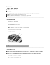
NOTE: This card is only compatible with your computer. Back to Contents Page Intel® Turbo Memory Dell™ Inspiron™ 1420/Dell Vostro™ 1400 Service Manual Removing the FCM Replacing the FCM The Intel Turbo Memory also called Flash Cache Module (FCM), is an internal flash drive...6. Follow the procedures in the WWAN slot. NOTE: If you return to the connector on the system board. 2. Remove the keyboard (see Removing the Keyboard Cover). 3. Installing the card on the back of these antenna cables may cause damage to your computer, the card is already ...
NOTE: This card is only compatible with your computer. Back to Contents Page Intel® Turbo Memory Dell™ Inspiron™ 1420/Dell Vostro™ 1400 Service Manual Removing the FCM Replacing the FCM The Intel Turbo Memory also called Flash Cache Module (FCM), is an internal flash drive...6. Follow the procedures in the WWAN slot. NOTE: If you return to the connector on the system board. 2. Remove the keyboard (see Removing the Keyboard Cover). 3. Installing the card on the back of these antenna cables may cause damage to your computer, the card is already ...

Service Manual
Page 23
Back to Contents Page Replace the keyboard cover (see Replacing the Keyboard). 4. Replace the keyboard (see Replacing the Keyboard Cover). 3.
Back to Contents Page Replace the keyboard cover (see Replacing the Keyboard). 4. Replace the keyboard (see Replacing the Keyboard Cover). 3.

Service Manual
Page 26
... not lift the cover on the right side. 4. NOTICE: To avoid damage to Contents Page Back to Contents Page Keyboard Cover Dell™ Inspiron™ 1420/Dell Vostro™ 1400 Service Manual Removing the Keyboard Cover Replacing the Keyboard Cover CAUTION: Before you begin working inside the computer. Press from left , and remove it will open. Open the...
... not lift the cover on the right side. 4. NOTICE: To avoid damage to Contents Page Back to Contents Page Keyboard Cover Dell™ Inspiron™ 1420/Dell Vostro™ 1400 Service Manual Removing the Keyboard Cover Replacing the Keyboard Cover CAUTION: Before you begin working inside the computer. Press from left , and remove it will open. Open the...

Service Manual
Page 27
... board. 6. Follow the procedures in the Product Information Guide. NOTICE: To help prevent damage to access the keyboard connector. 5. Back to Contents Page Keyboard Dell™ Inspiron™ 1420/Dell Vostro™ 1400 Service Manual Removing the Keyboard Replacing the Keyboard CAUTION: Before you begin any of the procedures in this section, follow the safety instructions in Before You...
... board. 6. Follow the procedures in the Product Information Guide. NOTICE: To help prevent damage to access the keyboard connector. 5. Back to Contents Page Keyboard Dell™ Inspiron™ 1420/Dell Vostro™ 1400 Service Manual Removing the Keyboard Replacing the Keyboard CAUTION: Before you begin any of the procedures in this section, follow the safety instructions in Before You...

Service Manual
Page 28
Replace the two screws to Contents Page 2. Hook the tabs along the front edge of the keyboard into place. 5. Back to secure the keyboard. Press on the right edge near the top to fasten the cable in the cable connector. 3. Rotate the cable release lever downward to snap the keyboard into the palmrest. 4.
Replace the two screws to Contents Page 2. Hook the tabs along the front edge of the keyboard into place. 5. Back to secure the keyboard. Press on the right edge near the top to fasten the cable in the cable connector. 3. Rotate the cable release lever downward to snap the keyboard into the palmrest. 4.


