
Reference Guide
Page 5
... Control Cards (LCCs 1-11 Disk Modules 1-12 Disk Drives 1-12 Drive Carrier 1-13 Power Supplies 1-13 Standby Power Supply (SPS 1-14 Drive Fan Pack 1-14 SP Fan Pack 1-15 Redundancy in Configurations 1-17 What Next 1-18 Installing a Rackmount DPE Requirements 2-1 Site Requirements 2-1 Cabling Requirements 2-2 Addressing Requirements 2-2 Installing a DPE in a Cabinet 2-3 Installing ...
... Control Cards (LCCs 1-11 Disk Modules 1-12 Disk Drives 1-12 Drive Carrier 1-13 Power Supplies 1-13 Standby Power Supply (SPS 1-14 Drive Fan Pack 1-14 SP Fan Pack 1-15 Redundancy in Configurations 1-17 What Next 1-18 Installing a Rackmount DPE Requirements 2-1 Site Requirements 2-1 Cabling Requirements 2-2 Addressing Requirements 2-2 Installing a DPE in a Cabinet 2-3 Installing ...

Reference Guide
Page 6
...Installing an Optical GBIC Connector 3-19 Removing an SP or an SP Filler Module 3-21 Installing or Replacing an SP Memory Module 3-24 Installing an SP or SP Filler Module 3-26 Installing an SP or SP Filler Module 3-27 Replacing or Adding an ... Module 3-41 Appendix A Technical Specifications and Operating Limits Technical Specifications A-1 AC Power Requirements A-1 Size and Weight A-2 Drive Type A-3 SP Optical Cabling A-3 LCC Copper Cabling A-3 Standards Certification and Compliance A-3 Operating Limits A-5 Shipping and Storage Requirements A-6 Glossary ...g-1 Index ...i-1...
...Installing an Optical GBIC Connector 3-19 Removing an SP or an SP Filler Module 3-21 Installing or Replacing an SP Memory Module 3-24 Installing an SP or SP Filler Module 3-26 Installing an SP or SP Filler Module 3-27 Replacing or Adding an ... Module 3-41 Appendix A Technical Specifications and Operating Limits Technical Specifications A-1 AC Power Requirements A-1 Size and Weight A-2 Drive Type A-3 SP Optical Cabling A-3 LCC Copper Cabling A-3 Standards Certification and Compliance A-3 Operating Limits A-5 Shipping and Storage Requirements A-6 Glossary ...g-1 Index ...i-1...

Reference Guide
Page 7
...View 1-7 1-5 DPE Back View with Drive Fan Pack Removed 1-7 1-6 Front Door ...1-9 1-7 SP Back Panel 1-10 1-8 LCC ...1-11 1-9 Disk Module 1-12 1-10 Power Supply 1-13 1-11 SPS ...1-14 1-12 Drive Fan Pack 1-15 1-13 SP Fan Pack 1-16 2-1 Opening the Front Door 2-5 2-2 Securing the DPE to the Cabinet Front... Channel 2-6 2-3 Securing the DPE to the Cabinet Back Channel 2-7 2-4 Closing and Locking the Front Door 2-8 2-5 SP Fibre Channel Arbitrated Loop Address ID Switches (Back of SP 2-10 2-6 Removing the Drive Fan Pack 2-11 2-7 Plugging the AC Line Cord into the Power Supply and Turning ...
...View 1-7 1-5 DPE Back View with Drive Fan Pack Removed 1-7 1-6 Front Door ...1-9 1-7 SP Back Panel 1-10 1-8 LCC ...1-11 1-9 Disk Module 1-12 1-10 Power Supply 1-13 1-11 SPS ...1-14 1-12 Drive Fan Pack 1-15 1-13 SP Fan Pack 1-16 2-1 Opening the Front Door 2-5 2-2 Securing the DPE to the Cabinet Front... Channel 2-6 2-3 Securing the DPE to the Cabinet Back Channel 2-7 2-4 Closing and Locking the Front Door 2-8 2-5 SP Fibre Channel Arbitrated Loop Address ID Switches (Back of SP 2-10 2-6 Removing the Drive Fan Pack 2-11 2-7 Plugging the AC Line Cord into the Power Supply and Turning ...

Reference Guide
Page 8
... Cover 3-17 3-11 Removing an Optical Cable from an SP 3-18 3-12 Removing an Optical GBIC Connector from an SP 3-19 3-13 Installing an Optical GBIC Connector on an SP 3-20 3-14 Installing an Optical Cable on an SP 3-21 3-15 Removing an SP or Filler Module 3-23 3-16 Removing the Memory Module ...from the SP 3-25 3-17 Installing the Memory Module on the SP 3-26 3-18 Setting the SP Address ID 3-28 3-19 Installing an SP or SP Filler Module 3-29 3-20 Removing an LCC ...
... Cover 3-17 3-11 Removing an Optical Cable from an SP 3-18 3-12 Removing an Optical GBIC Connector from an SP 3-19 3-13 Installing an Optical GBIC Connector on an SP 3-20 3-14 Installing an Optical Cable on an SP 3-21 3-15 Removing an SP or Filler Module 3-23 3-16 Removing the Memory Module ...from the SP 3-25 3-17 Installing the Memory Module on the SP 3-26 3-18 Setting the SP Address ID 3-28 3-19 Installing an SP or SP Filler Module 3-29 3-20 Removing an LCC ...
Reference Guide
Page 11
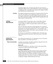
...How This Manual Is Organized This manual describes how to install the EMC Fibre Channel Disk-Array Processor Enclosure (DPE) Rackmount Model FC4500, and how to replace CRUs such as disk modules. Related Documentation Other EMC publications include: • EMC Fibre Channel Disk-...Array Enclosure (DAE) Rackmount Hardware Reference (P/N 014002591). • DC Standby Power Supply (SPS) Hardware Reference (P/N 014002887). Explains requirements and describes how to install the rackmount DPE and cable it , you will install and service the...
...How This Manual Is Organized This manual describes how to install the EMC Fibre Channel Disk-Array Processor Enclosure (DPE) Rackmount Model FC4500, and how to replace CRUs such as disk modules. Related Documentation Other EMC publications include: • EMC Fibre Channel Disk-...Array Enclosure (DAE) Rackmount Hardware Reference (P/N 014002591). • DC Standby Power Supply (SPS) Hardware Reference (P/N 014002887). Explains requirements and describes how to install the rackmount DPE and cable it , you will install and service the...

Reference Guide
Page 14
... Processor Enclosure 1 Introduction The DPE is a basic enclosure without a storage processor (SP). Its modular, scalable design provides additional disk storage as its interface, with simple FC-AL serial cabling, the FC4500 DPE can support up to 11 DAEs A DAE is a highly available, high-performance...storage system that uses a Fibre Channel Arbitrated Loop (FC-AL) as your needs increase. Figure 1-1 DAE Using its interconnect interface. The FC4500 and 11 DAEs support up to 120 disk modules in a single disk-array file storage system. 1-2 EMC Fibre Channel Disk-Array Processor...
... Processor Enclosure 1 Introduction The DPE is a basic enclosure without a storage processor (SP). Its modular, scalable design provides additional disk storage as its interface, with simple FC-AL serial cabling, the FC4500 DPE can support up to 11 DAEs A DAE is a highly available, high-performance...storage system that uses a Fibre Channel Arbitrated Loop (FC-AL) as your needs increase. Figure 1-1 DAE Using its interconnect interface. The FC4500 and 11 DAEs support up to 120 disk modules in a single disk-array file storage system. 1-2 EMC Fibre Channel Disk-Array Processor...

Reference Guide
Page 16
... and fan packs. The disk drives are customer-replaceable units (CRUs), which you can improve performance and connects easily to a second server. The SPs, LCCs, disk modules, power supplies, fan packs, and filler modules are FC-AL compliant and support dual-port FC-AL interconnects through the two ... Disk-Array Processor Enclosure 1 DPE Components The DPE components include: • A sheet-metal enclosure with a midplane, front door, and SP fan pack cover • One or two SPs • One or two link control cards (LCCs) • Up to ten disk modules • One or two power supplies &#...
... and fan packs. The disk drives are customer-replaceable units (CRUs), which you can improve performance and connects easily to a second server. The SPs, LCCs, disk modules, power supplies, fan packs, and filler modules are FC-AL compliant and support dual-port FC-AL interconnects through the two ... Disk-Array Processor Enclosure 1 DPE Components The DPE components include: • A sheet-metal enclosure with a midplane, front door, and SP fan pack cover • One or two SPs • One or two link control cards (LCCs) • Up to ten disk modules • One or two power supplies &#...

Reference Guide
Page 17
...in slot A is called component-name A. Di sk modu l e s 2 3456 7 8 9 01 Front door SP fan pack cover Figure 1-2 DPE Front View DPE Components 1-5 If you have one SP and one power supply, it is in either slot A or slot B. About the Rackmount Disk-Array Processor Enclosure 1 ...identical components, the component in either slot A or B, but not mixed. Component SP LCC Power supply Name in Slot A SP A LCC A PS A Name in Slot B SP B LCC B PS B If you have one LCC, they can be in slot B and is called component-nameB...
...in slot A is called component-name A. Di sk modu l e s 2 3456 7 8 9 01 Front door SP fan pack cover Figure 1-2 DPE Front View DPE Components 1-5 If you have one SP and one power supply, it is in either slot A or slot B. About the Rackmount Disk-Array Processor Enclosure 1 ...identical components, the component in either slot A or B, but not mixed. Component SP LCC Power supply Name in Slot A SP A LCC A PS A Name in Slot B SP B LCC B PS B If you have one LCC, they can be in slot B and is called component-nameB...

Reference Guide
Page 18
About the Rackmount Disk-Array Processor Enclosure 1 Front panel with door removed for clarity SP fan pack SP fan pack cover Figure 1-3 DPE Front View with SP Fan Cover and Door Removed 1-6 EMC Fibre Channel Disk-Array Processor Enclosure (DPE) Hardware Reference
About the Rackmount Disk-Array Processor Enclosure 1 Front panel with door removed for clarity SP fan pack SP fan pack cover Figure 1-3 DPE Front View with SP Fan Cover and Door Removed 1-6 EMC Fibre Channel Disk-Array Processor Enclosure (DPE) Hardware Reference

Reference Guide
Page 19
Class A Figure 1-5 DPE Back View with expansion connector (marked EXP) Figure 1-4 DPE Back View SP B SP ejector (2 per SP) LCC B with Drive Fan Pack Removed DPE Components 1-7 About the Rackmount Disk-Array Processor Enclosure 1 LCC A with expansion connector (marked EXP) Drive fan pack SP retaining screw (2 per SP) SP A ac line cord connectors Power supply PS A Power supply PS B LCC A LCC B SP B SP A Location of DPE EMI rating label -
Class A Figure 1-5 DPE Back View with expansion connector (marked EXP) Figure 1-4 DPE Back View SP B SP ejector (2 per SP) LCC B with Drive Fan Pack Removed DPE Components 1-7 About the Rackmount Disk-Array Processor Enclosure 1 LCC A with expansion connector (marked EXP) Drive fan pack SP retaining screw (2 per SP) SP A ac line cord connectors Power supply PS A Power supply PS B LCC A LCC B SP B SP A Location of DPE EMI rating label -

Reference Guide
Page 20
... each disk module slot, and two DPE status lights. This address cannot be changed. The midplane distributes power and signals to run SP A's disk modules; SP B works with LCC B to all the enclosure components. All lights are described in the "Monitoring DPE status" section in Chapter...3. The DPE status lights are visible with the front door closed. About the Rackmount Disk-Array Processor Enclosure 1 Front Panel SP A works with LCC A to run SP B's disk modules. All CRUs except the fan packs plug directly into midplane connectors. 1-8 EMC Fibre Channel Disk-Array Processor ...
... each disk module slot, and two DPE status lights. This address cannot be changed. The midplane distributes power and signals to run SP A's disk modules; SP B works with LCC B to all the enclosure components. All lights are described in the "Monitoring DPE status" section in Chapter...3. The DPE status lights are visible with the front door closed. About the Rackmount Disk-Array Processor Enclosure 1 Front Panel SP A works with LCC A to run SP B's disk modules. All CRUs except the fan packs plug directly into midplane connectors. 1-8 EMC Fibre Channel Disk-Array Processor ...

Reference Guide
Page 21
Opening the door to be closed for the DPE to access the disk modules is a service procedure. An SP is a printed-circuit board with dual in any DPE or DAE. When the door is the DPE's intelligent component. Figure 1-6 Front Door The front door ...has a locking latch and an EMI shield. Storage Processors (SPs) The SP is open, you can remove or install disk modules. DPE Components 1-9 It defines the DPE and differentiates the DPE from a DAE. Locking latch with key...
Opening the door to be closed for the DPE to access the disk modules is a service procedure. An SP is a printed-circuit board with dual in any DPE or DAE. When the door is the DPE's intelligent component. Figure 1-6 Front Door The front door ...has a locking latch and an EMI shield. Storage Processors (SPs) The SP is open, you can remove or install disk modules. DPE Components 1-9 It defines the DPE and differentiates the DPE from a DAE. Locking latch with key...

Reference Guide
Page 22
...come in a Fibre Channel Arbitrated Loop environment. Memory allocation is called the SP back end. The SP has two Fibre Channel ports (A and B) referred to as the SP front end, for connecting to LCC B. The SP-LCC interface is handled by Navisphere® Manager or another Navisphere array ...switches (required only for Fibre Channel Arbitrated Loop environment) Active light (green) Link/activity light Figure 1-7 SP Back Panel As shown in a fabric environment, only one of the SP ports (A or B) can be used to connect to the external Fibre Channel environment. When the DPE is...
...come in a Fibre Channel Arbitrated Loop environment. Memory allocation is called the SP back end. The SP has two Fibre Channel ports (A and B) referred to as the SP front end, for connecting to LCC B. The SP-LCC interface is handled by Navisphere® Manager or another Navisphere array ...switches (required only for Fibre Channel Arbitrated Loop environment) Active light (green) Link/activity light Figure 1-7 SP Back Panel As shown in a fabric environment, only one of the SP ports (A or B) can be used to connect to the external Fibre Channel environment. When the DPE is...

Reference Guide
Page 23
...to replace any of the DPE. Link Control Cards (LCCs) 1-11 Link Control Cards (LCCs) A link control card (LCC) is running .When both SPs are installed, you can install a second one while the DPE is running . Check light (amber) Active light (green) Latch Figure 1-8 LCC Each LCC... disk-module check lights. For a definition of the entire DPE, using special protocols. The LCC provides: • Fibre channel connectivity between the SP, disks, and other enclosures • Bypass capability for faulted or missing units • Monitor and control of the enclosure elements EXP Expansion FC-...
...to replace any of the DPE. Link Control Cards (LCCs) 1-11 Link Control Cards (LCCs) A link control card (LCC) is running .When both SPs are installed, you can install a second one while the DPE is running . Check light (amber) Active light (green) Latch Figure 1-8 LCC Each LCC... disk-module check lights. For a definition of the entire DPE, using special protocols. The LCC provides: • Fibre channel connectivity between the SP, disks, and other enclosures • Bypass capability for faulted or missing units • Monitor and control of the enclosure elements EXP Expansion FC-...

Reference Guide
Page 25
... lines have individual soft-start switches that slides into the enclosure slot guides and midplane connectors. The latch holds the disk module in the DPE's SPs. The power supplies (see figure below) are located behind the drive fan pack. Link Control Cards (LCCs) 1-13 With two power supplies, the top supply...
... lines have individual soft-start switches that slides into the enclosure slot guides and midplane connectors. The latch holds the disk module in the DPE's SPs. The power supplies (see figure below) are located behind the drive fan pack. Link Control Cards (LCCs) 1-13 With two power supplies, the top supply...

Reference Guide
Page 26
...to minimize acoustic noise. The drive fan pack contains three fans that use write caching, such as RAID 5, require a standby power supply (SPS) to prevent data loss during normal operation to compensate, resulting in the DPE. The drive fan pack connects directly to both power supplies, ...If a fan fails, the voltage and speed of Chapter 3. You can add or remove one power supply in the manual DC Standby Power Supply (SPS) Installation (014002887). A latch on the power supply locks it . About the Rackmount Disk-Array Processor Enclosure 1 Each power supply has status lights. ...
...to minimize acoustic noise. The drive fan pack contains three fans that use write caching, such as RAID 5, require a standby power supply (SPS) to prevent data loss during normal operation to compensate, resulting in the DPE. The drive fan pack connects directly to both power supplies, ...If a fan fails, the voltage and speed of Chapter 3. You can add or remove one power supply in the manual DC Standby Power Supply (SPS) Installation (014002887). A latch on the power supply locks it . About the Rackmount Disk-Array Processor Enclosure 1 Each power supply has status lights. ...

Reference Guide
Page 27
... Cards (LCCs) 1-15 Check light (amber) Latches Latches Figure 1-12 Drive Fan Pack The drive fan pack has one status light. The SP fan pack connects to the DPE midplane via an internal cable, and either supply can remove the drive fan pack while the DPE is described ...to minimize acoustic noise. The fans operate at a lower voltage and speed during normal operation to compensate, resulting in place. SP Fan Pack The SP fan pack (see Figure 1-12) cools the SPs. About the Rackmount Disk-Array Processor Enclosure 1 ! The status light is powered up when you reinstall the drive fan ...
... Cards (LCCs) 1-15 Check light (amber) Latches Latches Figure 1-12 Drive Fan Pack The drive fan pack has one status light. The SP fan pack connects to the DPE midplane via an internal cable, and either supply can remove the drive fan pack while the DPE is described ...to minimize acoustic noise. The fans operate at a lower voltage and speed during normal operation to compensate, resulting in place. SP Fan Pack The SP fan pack (see Figure 1-12) cools the SPs. About the Rackmount Disk-Array Processor Enclosure 1 ! The status light is powered up when you reinstall the drive fan ...

Reference Guide
Page 28
...light is powered up when you reinstall the SP fan pack. 1-16 EMC Fibre Channel Disk-Array Processor Enclosure (DPE) Hardware Reference About the Rackmount Disk-Array Processor Enclosure 1 Check light ! (amber) Latches Figure 1-13 SP Fan Pack Latches on the SP fan pack hold the pack in the "...Monitoring DPE Status" section of Chapter 3. The SP fan pack has one status light visible when the SP fan pack cover is removed for more than approximately two minutes...
...light is powered up when you reinstall the SP fan pack. 1-16 EMC Fibre Channel Disk-Array Processor Enclosure (DPE) Hardware Reference About the Rackmount Disk-Array Processor Enclosure 1 Check light ! (amber) Latches Figure 1-13 SP Fan Pack Latches on the SP fan pack hold the pack in the "...Monitoring DPE Status" section of Chapter 3. The SP fan pack has one status light visible when the SP fan pack cover is removed for more than approximately two minutes...

Reference Guide
Page 29
...Two LCCs in the DPE and each DAE • Disks in slots 0:0 through 0:8 • SPS (standby power supply) with equal memory of system availability. The drive fan packs and SP fan pack provide redundant cooling for caching (0 thru 8) The following table describes the DPE's high-...availability configurations. About the Rackmount Disk-Array Processor Enclosure 1 Redundancy in Configurations Mirrored storage-system write caching requires: • Two SPs with a fully charged battery DPE Rackmount 01 23 4 56 78 9 Database drives for LIC (0 thru 2) Vault drives for all the ...
...Two LCCs in the DPE and each DAE • Disks in slots 0:0 through 0:8 • SPS (standby power supply) with equal memory of system availability. The drive fan packs and SP fan pack provide redundant cooling for caching (0 thru 8) The following table describes the DPE's high-...availability configurations. About the Rackmount Disk-Array Processor Enclosure 1 Redundancy in Configurations Mirrored storage-system write caching requires: • Two SPs with a fully charged battery DPE Rackmount 01 23 4 56 78 9 Database drives for LIC (0 thru 2) Vault drives for all the ...
Reference Guide
Page 32
... connections to any connected DAEs. The optical cables connect to 2, and so on the Fibre Channel. DPE and DAE interconnections should connect the DPE's SP B (which connects internally to maintain the specified ambient temperature range. In a fabric environment, the DPE is , dangling) cable connected to the external...ambient temperature specification is a value that you might want to set the nearest DAE's EA to 1, the next to the optical GBIC on the SP. The DPE has a fixed EA of DPEs and DAEs that a switch in lights visible behind the front door. 2-2 EMC Fibre Channel Disk-...
... connections to any connected DAEs. The optical cables connect to 2, and so on the Fibre Channel. DPE and DAE interconnections should connect the DPE's SP B (which connects internally to maintain the specified ambient temperature range. In a fabric environment, the DPE is , dangling) cable connected to the external...ambient temperature specification is a value that you might want to set the nearest DAE's EA to 1, the next to the optical GBIC on the SP. The DPE has a fixed EA of DPEs and DAEs that a switch in lights visible behind the front door. 2-2 EMC Fibre Channel Disk-...
