
Setup and Quick Reference Guide
Page 21
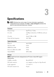
...Start→ Help and Support and select the option to view information about your computer. Processor Processor type L1 cache L2 cache Front side bus frequency Intel® Core™2 Duo 32 KB per instruction, 32 KB data cache per core shared 3 MB or 6 MB 1067 MHz System Information Chip set Data bus width ...DRAM bus width Processor address bus width Flash EPROM Intel GM45 64 bit 64 bit 36 ...
...Start→ Help and Support and select the option to view information about your computer. Processor Processor type L1 cache L2 cache Front side bus frequency Intel® Core™2 Duo 32 KB per instruction, 32 KB data cache per core shared 3 MB or 6 MB 1067 MHz System Information Chip set Data bus width ...DRAM bus width Processor address bus width Flash EPROM Intel GM45 64 bit 64 bit 36 ...

Setup and Quick Reference Guide
Page 22
...is reserved for system files. For more information about the memory connector see your computer's Service Manual at support.dell.com. NOTE: To enable Intel® Active Management Technology (iAMT), you must match in the memory connector... 64-bit Windows XP or Windows Vista operating system) NOTE: In order to the Dell™ Systems Management Administrator's Guide at support.dell.com. Ports and Connectors Audio IEEE 1394a microphone connector and stereo headphone/speakers connector 4-pin...) Memory type DDR2 800 MHz (if supported by chipset and/or processor combinations);
...is reserved for system files. For more information about the memory connector see your computer's Service Manual at support.dell.com. NOTE: To enable Intel® Active Management Technology (iAMT), you must match in the memory connector... 64-bit Windows XP or Windows Vista operating system) NOTE: In order to the Dell™ Systems Management Administrator's Guide at support.dell.com. Ports and Connectors Audio IEEE 1394a microphone connector and stereo headphone/speakers connector 4-pin...) Memory type DDR2 800 MHz (if supported by chipset and/or processor combinations);

Setup and Quick Reference Guide
Page 39
..., or no bootable device exists. • If the hard drive is your Service Manual at support.dell.com). HARD DRIVE SELF MONITORING SYSTEM HAS REPORTED THAT A PARAMETER HAS EXCEEDED ITS NORMAL OPERATING RANGE. Replace processor fan. See your boot device, ensure that the cables are connected and that the drive is installed...
..., or no bootable device exists. • If the hard drive is your Service Manual at support.dell.com). HARD DRIVE SELF MONITORING SYSTEM HAS REPORTED THAT A PARAMETER HAS EXCEEDED ITS NORMAL OPERATING RANGE. Replace processor fan. See your boot device, ensure that the cables are connected and that the drive is installed...

Setup and Quick Reference Guide
Page 43
... computer is receiving electrical power, a device might be malfunctioning or incorrectly installed. • Ensure that the processor power cable is securely connected to the system board connector (see "Beep Codes" on page 31. IF ... that the main power cable and the front panel cable are securely connected to the system board power connector (see your Service Manual at support.dell.com). If necessary, install additional memory (see if that resolves the problem. • See the software documentation for minimum memory requirements. I F T H E P O W ER L I G H T I S B L I N K I S ...
... computer is receiving electrical power, a device might be malfunctioning or incorrectly installed. • Ensure that the processor power cable is securely connected to the system board connector (see "Beep Codes" on page 31. IF ... that the main power cable and the front panel cable are securely connected to the system board power connector (see your Service Manual at support.dell.com). If necessary, install additional memory (see if that resolves the problem. • See the software documentation for minimum memory requirements. I F T H E P O W ER L I G H T I S B L I N K I S ...
Service Manual
Page 1
... potential for property damage, personal injury, or death. Information in the United States and/or other countries. Dell™ Latitude™ E6400 and E6400 ATG and Mobile Workstation Precision™ M2400 Service Manual Troubleshooting Working on Your Computer Base Assembly Hinge Covers Hard... Drive WLAN/WiMax Card WWAN Card WPAN (UWB/BT) Card FCM Fan Processor Heatsink Assembly Processor Module Memory Coin...
... potential for property damage, personal injury, or death. Information in the United States and/or other countries. Dell™ Latitude™ E6400 and E6400 ATG and Mobile Workstation Precision™ M2400 Service Manual Troubleshooting Working on Your Computer Base Assembly Hinge Covers Hard... Drive WLAN/WiMax Card WWAN Card WPAN (UWB/BT) Card FCM Fan Processor Heatsink Assembly Processor Module Memory Coin...
Service Manual
Page 2
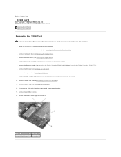
...). 4. Remove the palm rest assembly (Removing the Palm Rest Assembly). 11. Back to Contents Page 1394 Card Dell™ Latitude™ E6400 and E6400 ATG and Mobile Workstation Precision™ M2400 Service Manual Removing the 1394 Card Replacing the 1394 Card Removing the 1394... board 3 M2 x 3 screws (2) 4 1394 card Remove the heatsink assembly (see Removing the Keyboard). 9. Remove the keyboard (see Removing the Processor Heatsink Assembly). 6. Disconnect the 1394 cable from the system board, and unroute the cable. 13. Remove the card cage (see Removing the LED ...
...). 4. Remove the palm rest assembly (Removing the Palm Rest Assembly). 11. Back to Contents Page 1394 Card Dell™ Latitude™ E6400 and E6400 ATG and Mobile Workstation Precision™ M2400 Service Manual Removing the 1394 Card Replacing the 1394 Card Removing the 1394... board 3 M2 x 3 screws (2) 4 1394 card Remove the heatsink assembly (see Removing the Keyboard). 9. Remove the keyboard (see Removing the Processor Heatsink Assembly). 6. Disconnect the 1394 cable from the system board, and unroute the cable. 13. Remove the card cage (see Removing the LED ...
Service Manual
Page 3
Replace the palm rest assembly (Replacing the Palm Rest Assembly). 6. Replace the display assembly (see Replacing the Processor Heatsink Assembly). 11. Replace the heatsink assembly (see Replacing the Display Assembly (E6400 and M2400) or Replacing the Display Assembly (E6400 ATG)). 10. Replace the hinge covers (see Replacing the Keyboard). 8. Insert the 1394 card at...
Replace the palm rest assembly (Replacing the Palm Rest Assembly). 6. Replace the display assembly (see Replacing the Processor Heatsink Assembly). 11. Replace the heatsink assembly (see Replacing the Display Assembly (E6400 and M2400) or Replacing the Display Assembly (E6400 ATG)). 10. Replace the hinge covers (see Replacing the Keyboard). 8. Insert the 1394 card at...

Service Manual
Page 5
...the display assembly (see Replacing the Hard Drive). 14. Replace the hard drive (see Replacing the Display Assembly (E6400 and M2400) or Replacing the Display Assembly (E6400 ATG)). 12. Remove the display assembly (see Removing the Right Speaker Grill/Fingerprint Reader Assembly). 14. Remove ... in the WPAN/UWB/FCM card slot, if applicable (see Replacing the System Board Assembly). 5. Remove the keyboard (see Removing the Processor Heatsink Assembly). 8. Remove the heatsink assembly (see Removing the Keyboard). 13. Replace the heatsink assembly (see Replacing the Modular Drive). ...
...the display assembly (see Replacing the Hard Drive). 14. Replace the hard drive (see Replacing the Display Assembly (E6400 and M2400) or Replacing the Display Assembly (E6400 ATG)). 12. Remove the display assembly (see Removing the Right Speaker Grill/Fingerprint Reader Assembly). 14. Remove ... in the WPAN/UWB/FCM card slot, if applicable (see Replacing the System Board Assembly). 5. Remove the keyboard (see Removing the Processor Heatsink Assembly). 8. Remove the heatsink assembly (see Removing the Keyboard). 13. Replace the heatsink assembly (see Replacing the Modular Drive). ...
Service Manual
Page 7
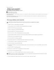
... from the alignment bracket, and remove the battery latch assembly. NOTICE: The spring is ready to Contents Page Battery Latch Assembly Dell™ Latitude™ E6400 and E6400 ATG and Mobile Workstation Precision™ M2400 Service Manual Removing a Battery Latch Assembly Replacing the Battery Latch Assembly There are different ... Remove the system board (see Removing the Palm Rest Assembly). 12. Do not remove the wireless mini-cards, memory modules, or processor from the system board. 14. Remove the RJ-11 modem connector (see Removing the RJ-11 Modem Connector). 16.
... from the alignment bracket, and remove the battery latch assembly. NOTICE: The spring is ready to Contents Page Battery Latch Assembly Dell™ Latitude™ E6400 and E6400 ATG and Mobile Workstation Precision™ M2400 Service Manual Removing a Battery Latch Assembly Replacing the Battery Latch Assembly There are different ... Remove the system board (see Removing the Palm Rest Assembly). 12. Do not remove the wireless mini-cards, memory modules, or processor from the system board. 14. Remove the RJ-11 modem connector (see Removing the RJ-11 Modem Connector). 16.
Service Manual
Page 8
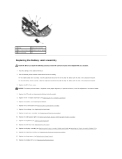
...left to align the button with the hole in the alignment bracket. Replace the card cage (see Replacing the Display Assembly (E6400 and M2400) or Replacing the Display Assembly (E6400 ATG)). 14. Replace the display assembly (see Replacing the Card Cage). 9. 1 spring 2 alignment bracket 3 M2 x... 6. Place the battery release button underneath the base assembly. Replace the M2 x 3-mm screw. Replace the modem (see Replacing the Processor Heatsink Assembly). 15. Replace the heatsink assembly (see Replacing the Modem). 7. Replace the keyboard (see Replacing the LED Cover). 13...
...left to align the button with the hole in the alignment bracket. Replace the card cage (see Replacing the Display Assembly (E6400 and M2400) or Replacing the Display Assembly (E6400 ATG)). 14. Replace the display assembly (see Replacing the Card Cage). 9. 1 spring 2 alignment bracket 3 M2 x... 6. Place the battery release button underneath the base assembly. Replace the M2 x 3-mm screw. Replace the modem (see Replacing the Processor Heatsink Assembly). 15. Replace the heatsink assembly (see Replacing the Modem). 7. Replace the keyboard (see Replacing the LED Cover). 13...
Service Manual
Page 10
...the components or contacts on your computer. Hold a card by its edges or by periodically touching an unpainted metal surface, such as a processor by its edges, not by your computer. Shut down . 6. Disconnect any of the computer. Slide the battery release latches toward each ... Handle components and cards with locking tabs, press inward on the locking tabs to Contents Page Working on Your Computer Dell™ Latitude™ E6400 and E6400 ATG and Mobile Workstation Precision™ M2400 Service Manual Recommended Tools Before Working on Your Computer After Working on its ...
...the components or contacts on your computer. Hold a card by its edges or by periodically touching an unpainted metal surface, such as a processor by its edges, not by your computer. Shut down . 6. Disconnect any of the computer. Slide the battery release latches toward each ... Handle components and cards with locking tabs, press inward on the locking tabs to Contents Page Working on Your Computer Dell™ Latitude™ E6400 and E6400 ATG and Mobile Workstation Precision™ M2400 Service Manual Recommended Tools Before Working on Your Computer After Working on its ...
Service Manual
Page 15
...Remove the palm rest assembly (Removing the Palm Rest Assembly). 11. Pivot the card cage up to Contents Page Card Cage Dell™ Latitude™ E6400 and E6400 ATG and Mobile Workstation Precision™ M2400 Service Manual Removing the Card Cage Replacing the Card Cage Removing the Card Cage CAUTION:...LED cover (see Removing the Modular Drive). 4. Remove the modular drive (see Removing the LED Cover). 8. Remove the hinge covers (see Removing the Processor Heatsink Assembly). 6. Back to a 45-degree angle, then lift it towards the back of the laptop. 14. If a card is in this ...
...Remove the palm rest assembly (Removing the Palm Rest Assembly). 11. Pivot the card cage up to Contents Page Card Cage Dell™ Latitude™ E6400 and E6400 ATG and Mobile Workstation Precision™ M2400 Service Manual Removing the Card Cage Replacing the Card Cage Removing the Card Cage CAUTION:...LED cover (see Removing the Modular Drive). 4. Remove the modular drive (see Removing the LED Cover). 8. Remove the hinge covers (see Removing the Processor Heatsink Assembly). 6. Back to a 45-degree angle, then lift it towards the back of the laptop. 14. If a card is in this ...
Service Manual
Page 16
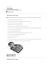
... two M2 x 3 screws. 1 M2 x 3 screws (2) 2 base assembly 3 front of the procedures in After Working on Your Computer. Replace the right speaker grill (see Replacing the Processor Heatsink Assembly). 9. Follow the procedures in this section, follow the safety instructions that shipped with your computer. 1. Replace the heatsink assembly (see Replacing the Right... card cage to Contents Page Holding the card cage at a 45-degree angle, attach the front of the base assembly (see Replacing the Display Assembly (E6400 and M2400) or Replacing the Display Assembly...
... two M2 x 3 screws. 1 M2 x 3 screws (2) 2 base assembly 3 front of the procedures in After Working on Your Computer. Replace the right speaker grill (see Replacing the Processor Heatsink Assembly). 9. Follow the procedures in this section, follow the safety instructions that shipped with your computer. 1. Replace the heatsink assembly (see Replacing the Right... card cage to Contents Page Holding the card cage at a 45-degree angle, attach the front of the base assembly (see Replacing the Display Assembly (E6400 and M2400) or Replacing the Display Assembly...
Service Manual
Page 19
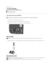
... capability of the Base Assembly). 3. NOTICE: When removing the processor module, pull the module straight up. Back to Contents Page Processor Module Dell™ Latitude™ E6400 and E6400 ATG and Mobile Workstation Precision™ M2400 Service Manual Removing the Processor Module Replacing the Processor Module Removing the Processor Module CAUTION: Before you begin the following procedure, follow the...
... capability of the Base Assembly). 3. NOTICE: When removing the processor module, pull the module straight up. Back to Contents Page Processor Module Dell™ Latitude™ E6400 and E6400 ATG and Mobile Workstation Precision™ M2400 Service Manual Removing the Processor Module Replacing the Processor Module Removing the Processor Module CAUTION: Before you begin the following procedure, follow the...

Service Manual
Page 20
...safety instructions that it is in an intermittent connection or permanent damage to the processor, hold the processor down on the substrate on the pin-1 corner of the ZIF socket. When the processor module is properly seated, all four corners are higher than the others, the... (see Replacing the Bottom of the ZIF socket, then insert the processor module. A processor module that the cam lock is perpendicular to prevent intermittent contact between the cam screw and processor. NOTE: If a new processor is installed, you will receive a new heatsink assembly, which the ...
...safety instructions that it is in an intermittent connection or permanent damage to the processor, hold the processor down on the substrate on the pin-1 corner of the ZIF socket. When the processor module is properly seated, all four corners are higher than the others, the... (see Replacing the Bottom of the ZIF socket, then insert the processor module. A processor module that the cam lock is perpendicular to prevent intermittent contact between the cam screw and processor. NOTE: If a new processor is installed, you will receive a new heatsink assembly, which the ...
Service Manual
Page 21
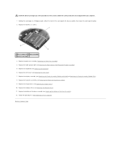
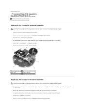
..., follow the safety instructions that shipped with your computer. 1. Back to Contents Page Processor Heatsink Assembly Dell™ Latitude™ E6400 and E6400 ATG and Mobile Workstation Precision™ M2400 Service Manual Removing the Processor Heatsink Assembly Replacing the Processor Heatsink Assembly Removing the Processor Heatsink Assembly CAUTION: Before you begin the following procedure, follow the safety instructions...
..., follow the safety instructions that shipped with your computer. 1. Back to Contents Page Processor Heatsink Assembly Dell™ Latitude™ E6400 and E6400 ATG and Mobile Workstation Precision™ M2400 Service Manual Removing the Processor Heatsink Assembly Replacing the Processor Heatsink Assembly Removing the Processor Heatsink Assembly CAUTION: Before you begin the following procedure, follow the safety instructions...
Service Manual
Page 23
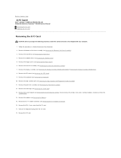
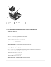
... plug from the I /O card. 18. Remove the heatsink assembly (see Removing the Hard Drive). 4. Back to Contents Page I/O Card Dell™ Latitude™ E6400 and E6400 ATG and Mobile Workstation Precision™ M2400 Service Manual Removing the I/O Card Replacing the I/O Card Removing the I /O card. Remove the M2...). 13. Remove the card cage (see Removing the LED Cover). 9. Do not remove the wireless mini-cards, memory modules, or processor from the system board. 14. Remove the right speaker grill (see Removing the System Board Assembly). Remove the system board (see Removing...
... plug from the I /O card. 18. Remove the heatsink assembly (see Removing the Hard Drive). 4. Back to Contents Page I/O Card Dell™ Latitude™ E6400 and E6400 ATG and Mobile Workstation Precision™ M2400 Service Manual Removing the I/O Card Replacing the I/O Card Removing the I /O card. Remove the M2...). 13. Remove the card cage (see Removing the LED Cover). 9. Do not remove the wireless mini-cards, memory modules, or processor from the system board. 14. Remove the right speaker grill (see Removing the System Board Assembly). Remove the system board (see Removing...
Service Manual
Page 24
... Replacing the Hinge Covers). 15. Replace the hinge covers (see Replacing the Display Assembly (E6400 and M2400) or Replacing the Display Assembly (E6400 ATG)). 13. Replace the plastic plug. 4. Replace the right speaker grill (see Replacing the Processor Heatsink Assembly). 14. Replace the heatsink assembly (see Replacing the Right Speaker Grill/Fingerprint Reader...
... Replacing the Hinge Covers). 15. Replace the hinge covers (see Replacing the Display Assembly (E6400 and M2400) or Replacing the Display Assembly (E6400 ATG)). 13. Replace the plastic plug. 4. Replace the right speaker grill (see Replacing the Processor Heatsink Assembly). 14. Replace the heatsink assembly (see Replacing the Right Speaker Grill/Fingerprint Reader...
Service Manual
Page 46
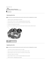
Back to Contents Page Fan Dell™ Latitude™ E6400 and E6400 ATG and Mobile Workstation Precision™ M2400 Service Manual Removing the Fan Replacing the Fan Removing the Fan CAUTION: Before you begin the following procedure, ... in Before Working on Your Computer. Follow the instructions in After Working on Your Computer. 2. Align the screws holes in the processor heatsink assembly. 3. Connect the fan cable to the processor heatsink assembly. 4. Remove the two M2.5 x 5-mm screws that shipped with the screw holes in the fan with your computer. 1. Lift...
Back to Contents Page Fan Dell™ Latitude™ E6400 and E6400 ATG and Mobile Workstation Precision™ M2400 Service Manual Removing the Fan Replacing the Fan Removing the Fan CAUTION: Before you begin the following procedure, ... in Before Working on Your Computer. Follow the instructions in After Working on Your Computer. 2. Align the screws holes in the processor heatsink assembly. 3. Connect the fan cable to the processor heatsink assembly. 4. Remove the two M2.5 x 5-mm screws that shipped with the screw holes in the fan with your computer. 1. Lift...
Service Manual
Page 72
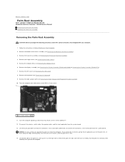
... the hinge covers (see Removing the Display Assembly (E6400 and M2400) or Removing the Display Assembly (E6400 ATG)). 7. Remove the display assembly (see Removing the Hinge Covers). 5. Remove the LED cover (see Removing the Processor Heatsink Assembly). 4. If you begin the following procedure... Assembly). 3. Remove the keyboard (see Removing the Modular Drive). 6. Back to Contents Page Palm Rest Assembly Dell™ Latitude™ E6400 and E6400 ATG and Mobile Workstation Precision™ M2400 Service Manual Removing the Palm Rest Assembly Replacing the Palm Rest Assembly Removing...
... the hinge covers (see Removing the Display Assembly (E6400 and M2400) or Removing the Display Assembly (E6400 ATG)). 7. Remove the display assembly (see Removing the Hinge Covers). 5. Remove the LED cover (see Removing the Processor Heatsink Assembly). 4. If you begin the following procedure... Assembly). 3. Remove the keyboard (see Removing the Modular Drive). 6. Back to Contents Page Palm Rest Assembly Dell™ Latitude™ E6400 and E6400 ATG and Mobile Workstation Precision™ M2400 Service Manual Removing the Palm Rest Assembly Replacing the Palm Rest Assembly Removing...


