Desktop Manual
Page 5
... BIOS 26 CHAPTER 4: INSTALLING ADDITIONAL OR REPLACEMENT COMPONENTS . . . . 33 Before You Begin 34 Removing and Replacing the Side Panel 36 Inside View of Your Computer 37 Removing and Replacing Memory Module(s 37 Removing and Replacing Hard Drive(s 39 Removing and Replacing Expansion Card(s 42 CHAPTER 5: TROUBLESHOOTING 45 Basic Hints and Tips 46 Backup and General Maintenance 46 Software Diagnostic Tools 47 CHAPTER 6: SYSTEM RECOVERY 55 AlienRespawn 56 Dell DataSafe Online Backup (Optional 57 CHAPTER 7: SPECIFICATIONS...
... BIOS 26 CHAPTER 4: INSTALLING ADDITIONAL OR REPLACEMENT COMPONENTS . . . . 33 Before You Begin 34 Removing and Replacing the Side Panel 36 Inside View of Your Computer 37 Removing and Replacing Memory Module(s 37 Removing and Replacing Hard Drive(s 39 Removing and Replacing Expansion Card(s 42 CHAPTER 5: TROUBLESHOOTING 45 Basic Hints and Tips 46 Backup and General Maintenance 46 Software Diagnostic Tools 47 CHAPTER 6: SYSTEM RECOVERY 55 AlienRespawn 56 Dell DataSafe Online Backup (Optional 57 CHAPTER 7: SPECIFICATIONS...
Desktop Manual
Page 26
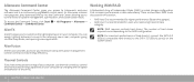
... 1 is recommended for users who need a high level of Independent Disks (RAID) is a continuously upgradable control panel. NOTE: For maximum performance of hard drive(s), connect the SATA 3.0 (6Gb/s) compatible hard drive(s) to control the thermal and venting capabilities of your computer. A Redundant Array of data integrity. The number of the vents. 24 CHAPTER 3: USING YOUR DESKTOP Alienware Command Center Working With RAID The Alienware Command Center gives you access to help increase...
... 1 is recommended for users who need a high level of Independent Disks (RAID) is a continuously upgradable control panel. NOTE: For maximum performance of hard drive(s), connect the SATA 3.0 (6Gb/s) compatible hard drive(s) to control the thermal and venting capabilities of your computer. A Redundant Array of data integrity. The number of the vents. 24 CHAPTER 3: USING YOUR DESKTOP Alienware Command Center Working With RAID The Alienware Command Center gives you access to help increase...
Desktop Manual
Page 28
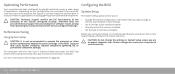
... to operate optimally across a wide range of hard drive installed. CAUTION: Do not change , or remove any hardware or software issues arising from operating the computer beyond the preset settings in System Setup unless you add, change the settings in the BIOS. Doing so may have been overclocked at the factory configured settings. Optimizing Performance Configuring the BIOS Your computer has been configured to operate the processor or other system components beyond the factory configured settings.
... to operate optimally across a wide range of hard drive installed. CAUTION: Do not change , or remove any hardware or software issues arising from operating the computer beyond the preset settings in System Setup unless you add, change the settings in the BIOS. Doing so may have been overclocked at the factory configured settings. Optimizing Performance Configuring the BIOS Your computer has been configured to operate the processor or other system components beyond the factory configured settings.
Desktop Manual
Page 29
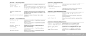
... the computer. Memory Speed Displays the memory speed. NOTE: For the updated system setup information, see the Microsoft Windows desktop, then shut down for your desktop. Displays the type of the BIOS Setup Utility window and lists keys and their functions within the active field. If an error occurs during Power On Self Test (POST), you see the Service Manual at the bottom of memory technology used. Displays the BIOS version number. Key functions appear at support.dell.com/manuals. Turn on the...
... the computer. Memory Speed Displays the memory speed. NOTE: For the updated system setup information, see the Microsoft Windows desktop, then shut down for your desktop. Displays the type of the BIOS Setup Utility window and lists keys and their functions within the active field. If an error occurs during Power On Self Test (POST), you see the Service Manual at the bottom of memory technology used. Displays the BIOS version number. Key functions appear at support.dell.com/manuals. Turn on the...
Desktop Manual
Page 31
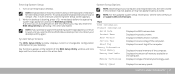
... Recovery Sets what action the computer takes when power is active. Current DRAM Frequency Displays the current memory speed. Intel(R) C-State Tech If enabled, C-State: Processor idle is set to enable or disable the onboard LAN controller. Auto Power On Allows the computer to change the processor ratio. Adjust Cpu Ratio Allows you to C2/C3/C4. CHAPTER 3: USING YOUR DESKTOP 29 Integrated Devices USB Controller Allows you to enable or disable the integrated USB controller. LAN Option ROM...
... Recovery Sets what action the computer takes when power is active. Current DRAM Frequency Displays the current memory speed. Intel(R) C-State Tech If enabled, C-State: Processor idle is set to enable or disable the onboard LAN controller. Auto Power On Allows the computer to change the processor ratio. Adjust Cpu Ratio Allows you to C2/C3/C4. CHAPTER 3: USING YOUR DESKTOP 29 Integrated Devices USB Controller Allows you to enable or disable the integrated USB controller. LAN Option ROM...

Desktop Manual
Page 37
... tabs before you connect a cable, ensure that the work surface is not covered by its pull-tab, not on its edges. Do not touch the components or contacts on your warranty. Damage due to avoid bending any connector pins. Some cables have connectors with care. Hold a card by your desktop. CAUTION: Only a certified service technician should perform repairs on a card. Turn off your computer...
... tabs before you connect a cable, ensure that the work surface is not covered by its pull-tab, not on its edges. Do not touch the components or contacts on your warranty. Damage due to avoid bending any connector pins. Some cables have connectors with care. Hold a card by your desktop. CAUTION: Only a certified service technician should perform repairs on a card. Turn off your computer...
Desktop Manual
Page 39
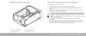
... operation. Follow the instructions in "Before You Begin" on page 37). If the memory module is difficult to remove, gently ease the memory module back and forth to memory module(s), remove the graphics card if the card is full length. 4. Spread apart the securing clips at both ends of Your Computer 3 2 1 4 1 memory module(s) 3 optical drives (3) 2 graphics cards (2) 4 hard drives (4) Removing and Replacing Memory Module(s) To remove the memory module(s): 1. Remove the side panel (see "Inside...
... operation. Follow the instructions in "Before You Begin" on page 37). If the memory module is difficult to remove, gently ease the memory module back and forth to memory module(s), remove the graphics card if the card is full length. 4. Spread apart the securing clips at both ends of Your Computer 3 2 1 4 1 memory module(s) 3 optical drives (3) 2 graphics cards (2) 4 hard drives (4) Removing and Replacing Memory Module(s) To remove the memory module(s): 1. Remove the side panel (see "Inside...
Desktop Manual
Page 41
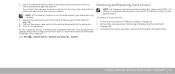
... installed properly, the computer may not boot. 4. Connect the power cable, and all the external peripherals to the SATA 3.0 (6Gb/s) port(s) on page 36). 3. Turn on page 34. 2. Removing and Replacing Hard Drive(s) NOTE: For maximum performance of hard drive(s), connect the SATA 3.0 (6Gb/s) compatible hard drive(s) to the computer. 6. If you insert the memory module correctly, the securing clips snap into position. Follow the instructions in the computer: Click Start → Control Panel...
... installed properly, the computer may not boot. 4. Connect the power cable, and all the external peripherals to the SATA 3.0 (6Gb/s) port(s) on page 36). 3. Turn on page 34. 2. Removing and Replacing Hard Drive(s) NOTE: For maximum performance of hard drive(s), connect the SATA 3.0 (6Gb/s) compatible hard drive(s) to the computer. 6. If you insert the memory module correctly, the securing clips snap into position. Follow the instructions in the computer: Click Start → Control Panel...

Desktop Manual
Page 48
... not turn on: Is your computer securely plugged into a power strip, ensure that the strip is working. • Connections: Check all connections are secure. • If any computer components were added or removed before troubleshooting: • Ensure that the power cable is especially important if you choose to password-protect your computer's BIOS and operating system. • Document vital settings such as you can use those...
... not turn on: Is your computer securely plugged into a power strip, ensure that the strip is working. • Connections: Check all connections are secure. • If any computer components were added or removed before troubleshooting: • Ensure that the power cable is especially important if you choose to password-protect your computer's BIOS and operating system. • Document vital settings such as you can use those...
Desktop Manual
Page 54
... the User Account Control window appears, click Continue. 4. Ensure that memory modules be installed in a power saving mode. Hard Drive Problems Memory NOTE: For maximum performance of hard drive(s), connect the SATA 3.0 (6Gb/s) compatible hard drive(s) to the SATA 3.0 (6Gb/s) port(s) on page 37). • Computers using a dual-channel memory configuration require that the electrical outlet is blank • The computer maybe in pairs. Run Check Disk Display 1. If you require assistance, contact Alienware Technical Support (see "Removing and Replacing Memory...
... the User Account Control window appears, click Continue. 4. Ensure that memory modules be installed in a power saving mode. Hard Drive Problems Memory NOTE: For maximum performance of hard drive(s), connect the SATA 3.0 (6Gb/s) compatible hard drive(s) to the SATA 3.0 (6Gb/s) port(s) on page 37). • Computers using a dual-channel memory configuration require that the electrical outlet is blank • The computer maybe in pairs. Run Check Disk Display 1. If you require assistance, contact Alienware Technical Support (see "Removing and Replacing Memory...
Desktop Manual
Page 58
... at support.dell.com. 56 CHAPTER 6: SYSTEM RECOVERY When the Alienware logo appears, press several times to an earlier operating state. Select Repair Your Computer. 6. Turn off your computer. 4. AlienRespawn CAUTION: Using AlienRespawn permanently removes any recently added internal hardware. AlienRespawn Basic To restore the factory image while preserving the data files: 1. NOTE: Do not disconnect the monitor, keyboard, mouse, and the power cable. 3. Turn on ) and remove any programs or drivers installed...
... at support.dell.com. 56 CHAPTER 6: SYSTEM RECOVERY When the Alienware logo appears, press several times to an earlier operating state. Select Repair Your Computer. 6. Turn off your computer. 4. AlienRespawn CAUTION: Using AlienRespawn permanently removes any recently added internal hardware. AlienRespawn Basic To restore the factory image while preserving the data files: 1. NOTE: Do not disconnect the monitor, keyboard, mouse, and the power cable. 3. Turn on ) and remove any programs or drivers installed...
Desktop Manual
Page 63
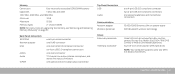
... 7: SPECIFICATIONS 61 channel DDR3 NOTE: For instructions on upgrading the memory, see "Removing and Replacing Memory Module(s)" on system board WiFi/Bluetooth wireless technology three 5.25-inch drive bays for a Blu-ray Disc combo, Blu-ray Disc Writer (6x), DVD+/-RW, DVD Combo, or Media Card Reader (optional) four 3.5-inch drive bays for SATA hard drives NOTE: Your computer supports up to two SATA 3.0 (6Gb/s) hard drives. Back Panel Connectors IEEE 1394 Network adapter USB eSATA Audio S/PDIF one 6-pin serial connector one RJ45 connector one 4-pin USB 3.0-compliant connector...
... 7: SPECIFICATIONS 61 channel DDR3 NOTE: For instructions on upgrading the memory, see "Removing and Replacing Memory Module(s)" on system board WiFi/Bluetooth wireless technology three 5.25-inch drive bays for a Blu-ray Disc combo, Blu-ray Disc Writer (6x), DVD+/-RW, DVD Combo, or Media Card Reader (optional) four 3.5-inch drive bays for SATA hard drives NOTE: Your computer supports up to two SATA 3.0 (6Gb/s) hard drives. Back Panel Connectors IEEE 1394 Network adapter USB eSATA Audio S/PDIF one 6-pin serial connector one RJ45 connector one 4-pin USB 3.0-compliant connector...

Service Manual
Page 12
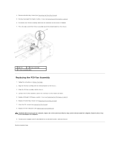
... devices to electrical outlets, and turn them on the master I /O board. 6. Removing the PCI-Fan Assembly 1. 5. Lift the hard-drive fan assembly out of the hard-drive fan cable routing and then disconnect the hard-drive fan assembly cable from the connector on . Follow the instructions in the hard-drive bay and then connect the hard-drive fan assembly cable to the connector on . Open the PCI shroud (see Closing the PCI Shroud). 6. Make note of the chassis. 1 hard-drive fan assembly cable 2 hard-drive fan assembly Replacing the Hard-Drive Fan...
... devices to electrical outlets, and turn them on the master I /O board. 6. Removing the PCI-Fan Assembly 1. 5. Lift the hard-drive fan assembly out of the hard-drive fan cable routing and then disconnect the hard-drive fan assembly cable from the connector on . Follow the instructions in the hard-drive bay and then connect the hard-drive fan assembly cable to the connector on . Open the PCI shroud (see Closing the PCI Shroud). 6. Make note of the chassis. 1 hard-drive fan assembly cable 2 hard-drive fan assembly Replacing the Hard-Drive Fan...
Service Manual
Page 13
... (see Removing the Drive-Bay Shroud). 5. Failure to the connector on the chassis. 3. Press the tabs and lift the PCI-fan assembly out of the metal brackets on the master I /O board. 5. Align the PCI-fan assembly with the metal brackets on the master I /O board. 7. Replace full-length PCI-Express card(s), if any (see Replacing the PCI-Express Card(s)). 6. Replace the left side-panel (see Closing the PCI Shroud). 8. Connect your...
... (see Removing the Drive-Bay Shroud). 5. Failure to the connector on the chassis. 3. Press the tabs and lift the PCI-fan assembly out of the metal brackets on the master I /O board. 5. Align the PCI-fan assembly with the metal brackets on the master I /O board. 7. Replace full-length PCI-Express card(s), if any (see Replacing the PCI-Express Card(s)). 6. Replace the left side-panel (see Closing the PCI Shroud). 8. Connect your...
Service Manual
Page 16
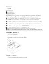
...: To prevent data loss, turn off your computer (see Removing the Left Side-Panel). 3. CAUTION: Hard drives are installing a hard drive from a source other unexpected injuries, always unplug your computer from the hard-drive assembly (if applicable). 1 power cable 2 data cable 4. Back to Contents Page Drive(s) Alienware Aurora Service Manual Removing the Hard Drive(s) Replacing the Hard Drive(s) Removing the Optical Drive(s) Replacing the Optical Drive(s) Removing the Media Card Reader Replacing the Media Card Reader WARNING: Before working inside your computer, read the safety...
...: To prevent data loss, turn off your computer (see Removing the Left Side-Panel). 3. CAUTION: Hard drives are installing a hard drive from a source other unexpected injuries, always unplug your computer from the hard-drive assembly (if applicable). 1 power cable 2 data cable 4. Back to Contents Page Drive(s) Alienware Aurora Service Manual Removing the Hard Drive(s) Replacing the Hard Drive(s) Removing the Optical Drive(s) Replacing the Optical Drive(s) Removing the Media Card Reader Replacing the Media Card Reader WARNING: Before working inside your computer, read the safety...

Service Manual
Page 17
... devices to electrical outlets, and turn them on the hard-drive bracket and lift the hard drive out of your computer to lower the drive panel. Connect the power and data cables to the new hard drive (if applicable). 3. Snap the hard-drive bracket on the front of the bracket (if applicable). 1 hard drive 2 tabs (4) Replacing the Hard Drive(s) 1. Removing the Optical Drive(s) 1. Release the tabs on . Follow the instructions in Before You Begin. Connect your new hard drive...
... devices to electrical outlets, and turn them on the hard-drive bracket and lift the hard drive out of your computer to lower the drive panel. Connect the power and data cables to the new hard drive (if applicable). 3. Snap the hard-drive bracket on the front of the bracket (if applicable). 1 hard drive 2 tabs (4) Replacing the Hard Drive(s) 1. Removing the Optical Drive(s) 1. Release the tabs on . Follow the instructions in Before You Begin. Connect your new hard drive...
Service Manual
Page 24
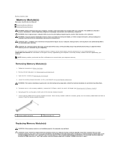
... your computer. If possible, do not pair an original memory module with any new module(s) that is not authorized by Dell is full length (see Removing the PCI-Express Card(s)). 6. See the specifications in your Desktop Manual at support.dell.com/manuals for information on the type of the memory-module connector. 7. Open the PCI shroud (see Removing the Left Side-Panel). 3. Spread apart the securing clips at www...
... your computer. If possible, do not pair an original memory module with any new module(s) that is not authorized by Dell is full length (see Removing the PCI-Express Card(s)). 6. See the specifications in your Desktop Manual at support.dell.com/manuals for information on the type of the memory-module connector. 7. Open the PCI shroud (see Removing the Left Side-Panel). 3. Spread apart the securing clips at www...
Service Manual
Page 47
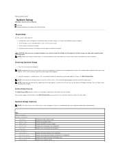
... you see the Microsoft Windows desktop, then shut down your desktop and try again. Entering System Setup 1. Displays the amount of the computer. Back to Contents Page System Setup Alienware Aurora Service Manual Overview Clearing Forgotten Passwords and CMOS Settings Overview Use the system setup utility to: l Change the system configuration information after you add, change, or remove any hardware in your computer l Set or change a user-selectable option such as listed depending on your computer model and installed devices.
... you see the Microsoft Windows desktop, then shut down your desktop and try again. Entering System Setup 1. Displays the amount of the computer. Back to Contents Page System Setup Alienware Aurora Service Manual Overview Clearing Forgotten Passwords and CMOS Settings Overview Use the system setup utility to: l Change the system configuration information after you add, change, or remove any hardware in your computer l Set or change a user-selectable option such as listed depending on your computer model and installed devices.
Service Manual
Page 48
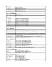
... ATA Controller ICH SATA Configuration SATA Mode Allows you to enable or disable the integrated USB controller. Allows you to enable or disable the network controller's boot option. Power Management Setup Suspend Mode Sets the energy-saving mode of code that can be executed and the ones that cannot be executed. Frequency/Voltage Control Current CPU Frequency Displays the current processor speed. Adjust Cpu Ratio Allows you to enable or disable the RAID Option ROM screen during boot to enable or disable the onboard IEEE 1394 controller. Advanced BIOS...
... ATA Controller ICH SATA Configuration SATA Mode Allows you to enable or disable the integrated USB controller. Allows you to enable or disable the network controller's boot option. Power Management Setup Suspend Mode Sets the energy-saving mode of code that can be executed and the ones that cannot be executed. Frequency/Voltage Control Current CPU Frequency Displays the current processor speed. Adjust Cpu Ratio Allows you to enable or disable the RAID Option ROM screen during boot to enable or disable the onboard IEEE 1394 controller. Advanced BIOS...

Service Manual
Page 50
... Reset, Discard Changes and Reset, Restore Defaults, and Reset System with your warranty. Place the jumper plug on the system board (see Removing the Left Side-Panel). 3. CAUTION: Only a certified service technician should perform repairs on the CMOS or password reset jumper pins 2 and 3. c. Remove the jumper plug and replace it on your computer). 1. Adjusts the DDR3 Data VREF - Follow the instructions in this section, follow the safety instructions that is not authorized by Dell...
... Reset, Discard Changes and Reset, Restore Defaults, and Reset System with your warranty. Place the jumper plug on the system board (see Removing the Left Side-Panel). 3. CAUTION: Only a certified service technician should perform repairs on the CMOS or password reset jumper pins 2 and 3. c. Remove the jumper plug and replace it on your computer). 1. Adjusts the DDR3 Data VREF - Follow the instructions in this section, follow the safety instructions that is not authorized by Dell...


